
The SMD Assembly Dilemma: Budget vs. Scale in 2026
As surface-mount devices (SMD) continue to shrink, with 0201 and 01005 packages becoming standard even in hobbyist and prosumer designs, manual soldering with an iron is no longer viable for complex boards. While commercial reflow ovens offer perfect thermal profiling, their $2,000+ price tags and massive footprints are unjustifiable for low-volume prototyping or small-batch manufacturing. This is where hot plate soldering emerges as the ultimate middle ground. However, deciding whether to use a hot plate, a hot air rework station, or invest in a desktop reflow oven requires a structured approach. This decision framework will help you evaluate thermal mass, component density, and budget to determine if hot plate reflow is the right choice for your next PCB assembly run.
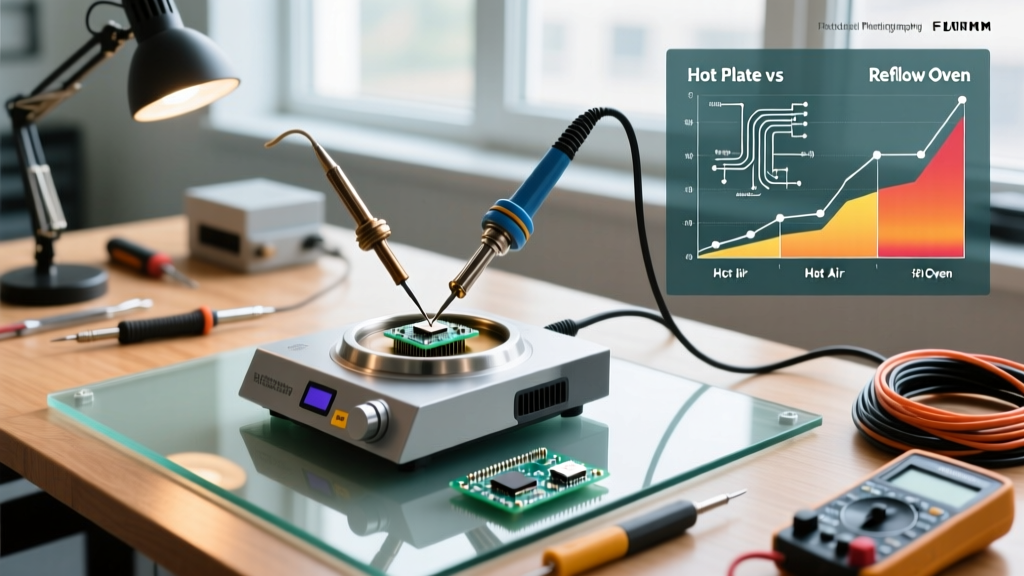
Decision Matrix: Hot Plate vs. Alternatives
Before committing to a method, evaluate your project against the following matrix. Hot plate soldering excels in specific scenarios but falls short in others, particularly when dealing with complex multi-layer boards or hidden BGA (Ball Grid Array) joints.
| Method | Setup Cost (2026) | Throughput | Max Board Size | Best Use Case |
|---|---|---|---|---|
| Hot Plate Soldering | $30 - $160 | Low (1-5 boards/batch) | Small to Medium (< 100x100mm) | Prototyping, small batches, mixed SMD/THD prep |
| Hot Air Rework | $100 - $350 | Very Low (1 board) | Targeted Areas Only | Rework, single-board prototyping, QFN/BGA touch-ups |
| Desktop Reflow Oven | $600 - $1,500 | Medium (Batch/Continuous) | Large (up to 300x300mm) | Small-batch production, complex multi-layer boards |
| Commercial Conveyor Oven | $3,000+ | High (Continuous) | Unlimited | Mass manufacturing, IPC-certified production lines |
When Hot Plate Soldering is the Optimal Choice
Hot plate reflow is not a universal panacea. It is highly recommended under the following conditions:
- High Thermal Mass Ground Planes: If your PCB features large exposed copper pours connected to ground, a hot air gun will struggle to heat the entire pad evenly, leading to cold joints. A hot plate heats the board from the bottom up, equalizing the thermal mass across the entire substrate.
- Bottom-Terminated Components (BTCs): QFNs (Quad Flat No-leads) and LGAs require uniform heat to ensure the thermal pad solders correctly without creating voids. Bottom-up hot plate heating is vastly superior to top-down hot air for these specific ICs.
- Simultaneous SMD and Through-Hole Preparation: Hot plates are excellent for pre-tinning through-hole pads or reflowing SMD components on the top layer while leaving the bottom layer untouched for subsequent wave soldering.
Pro-Tip for 2026 PCB Design: If you plan to use hot plate soldering, design your PCBs with thermal reliefs on all vias connected to SMD pads. Without thermal reliefs, the via will act as a heat sink, pulling thermal energy away from the pad and causing the component to 'tombstone' during reflow.
Hardware Selection: From Kitchen Burners to Lab Plates
The market for hot plates ranges from dangerously uncontrolled kitchen appliances to precision laboratory equipment. Your choice dictates your yield rate.
1. The Budget Route: Generic 500W-1000W Hot Plates ($25 - $50)
Brands like VEVOR or generic Amazon single-burners are popular among hobbyists. The catch: They use mechanical bimetallic thermostats with massive hysteresis (temperature swings of ±30°C). You cannot rely on the built-in dial. You must use an external infrared thermometer or a K-type thermocouple taped to a sacrificial PCB to manually monitor the temperature, lifting the board off the plate with tweezers once the solder paste flashes to liquidus.
2. The Prosumer Lab Plate: Magnetic Stirrer Hotplates ($90 - $160)
Lab-grade hot plates (e.g., Aoyue 853A Pre-heater/Hotplate or VEVOR Magnetic Stirrers) offer digital PID temperature control, maintaining the surface temperature within ±2°C. While designed for chemistry, their flat ceramic or glass tops provide the even heat distribution required for SMD soldering. The Aoyue 853A, priced around $140, is a staple in hacker spaces specifically because it can hold a steady 150°C soak temperature without overshooting.
Thermal Profiling and Solder Paste Chemistry
Success in hot plate soldering hinges on understanding your solder paste's chemical flux activation and alloy melting points. According to the guidelines outlined in IPC J-STD-001, achieving a proper metallurgical bond requires strict adherence to Time Above Liquidus (TAL).
Leaded vs. Lead-Free Paste Selection
- Chip Quik SMD291AX (Sn63/Pb37): Melts at 183°C. The eutectic nature of this alloy means it transitions instantly from solid to liquid without a plastic (semi-solid) phase. This drastically reduces the risk of disturbed joints if the board is bumped during cooling. Ideal for hot plates due to the lower peak temperature requirement.
- Kester 275 or SAC305 (Sn96.5/Ag3.0/Cu0.5): Melts at 217°C. Requires a peak temperature of 235°C - 245°C. Hot plate soldering with lead-free paste is riskier for hobbyists because standard FR-4 PCBs (with a Glass Transition Temperature, Tg, of 130°C) can delaminate or warp if held at 240°C for too long. If using lead-free, specify High-Tg (170°C+) FR-4 material from your fab house.
Execution Protocol: A Step-by-Step Reflow Flow
- Preparation: Bake your PCBs at 100°C for 30 minutes before assembly to drive out absorbed moisture. Moisture trapped in the FR-4 substrate will vaporize during reflow, causing micro-cracking or 'popcorning' in IC packages.
- Stenciling: Apply solder paste using a laser-cut stainless steel stencil. For hot plate reflow, slightly reduce the stencil aperture (by 10%) to prevent solder balling caused by the slower ramp rates of hot plates compared to forced-convection ovens.
- Placement: Use precision tweezers or a vacuum pen to place components. The surface tension of the molten solder will self-align the components, provided the pads are symmetrical.
- The Ramp and Soak: Place the board on the hot plate pre-set to 120°C. Allow the board to soak for 60-90 seconds. This activates the flux, cleaning the oxidation off the pads, and prevents thermal shock.
- The Reflow Peak: Increase the hot plate temperature (or move the board to a second, hotter plate set to 220°C for leaded paste). Watch closely. The paste will turn dull, then suddenly flash to a shiny silver liquid. Maintain this state for 45 to 60 seconds (the TAL).
- Controlled Cooling: Using silicone-tipped tweezers or a high-temp spatula, transfer the board to a heat-resistant ceramic mat. Never quench the board with compressed air or water. Rapid cooling induces micro-fractures in the solder joints and stresses ceramic capacitors.
Critical Failure Modes and Troubleshooting
Even with perfect execution, hot plate soldering introduces unique failure modes that reflow soldering engineers must mitigate:
- Tombstoning (Drawbridging): One side of a 2-terminal component (like a 0603 resistor) lifts off the pad. Cause: Uneven heating. If one pad is connected to a massive ground plane and the other to a thin trace, the thin trace pad reaches liquidus first. The surface tension of the molten solder pulls the component upright. Fix: Implement thermal reliefs in your CAD software.
- Solder Balling: Tiny spheres of solder form around the IC pins. Cause: Moisture in the solder paste or an excessively fast ramp rate that causes the flux to boil and splatter molten solder. Fix: Store paste in a syringe cooler and extend the 120°C soak time.
- Cold Joints: Dull, grainy solder joints that fail under mechanical stress. Cause: The board was removed from the hot plate before the entire thermal mass of the component leads reached the liquidus temperature. Fix: Trust your thermocouple data, not just the visual shine of the paste.
Final Verdict
Hot plate soldering remains an indispensable technique in the 2026 electronics workbench. By understanding the thermal limitations of your substrate, selecting the correct eutectic alloy, and utilizing a PID-controlled lab plate, you can achieve near-factory yields for small-batch SMD assembly without the capital expenditure of a commercial reflow oven. Evaluate your board's thermal mass, respect the TAL, and let the physics of surface tension do the heavy lifting.