
The Reality of Micro-Audio Soldering
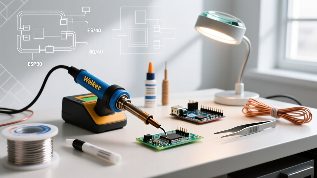
Headphone jack soldering is often treated as a beginner project, but the miniaturization of modern audio connectors has turned it into a precision task. Whether you are repairing a vintage pair of Sennheiser HD600s with a 1/4-inch TRS plug or custom-wiring a 3.5mm TRRS inline microphone cable, the physical tolerances are unforgiving. Signal lugs on 3.5mm jacks (like the widely used CUI Devices SJ-4350x series) are often spaced less than 2mm apart. A fraction of a millimeter of excess solder or a two-second over-application of heat can result in channel bleed, melted dielectrics, or catastrophic pad lift-off.
This guide bypasses the basic 'tin the wire' advice and dives straight into advanced troubleshooting, thermal management, and failure analysis for audio connectors in 2026.
Headphone Jack Troubleshooting Matrix
Before grabbing your desoldering iron, diagnose the exact failure mode. Use this matrix to map your audio symptoms to physical soldering defects.
| Symptom | Root Cause | Diagnostic Method | Targeted Solution |
|---|---|---|---|
| Audio cuts out when cable bends | Solder wicking / Stress fracture | Visual inspection of wire entry; flex test | Re-strip wire to 3mm; apply adhesive-lined heat shrink |
| Left channel bleeds into Right | Solder bridge between Tip and Ring | Multimeter continuity test (Tip to Ring lugs) | Use 0.020" desoldering braid and 99% IPA |
| Hollow, out-of-phase audio | CTIA vs. OMTP TRRS pinout mismatch | Verify mic and ground continuity on Sleeve/Ring 2 | Rewire according to device standard (CTIA/OMTP) |
| Muffled audio / Missing highs | Cold joint or Ground loop on Sleeve | Wiggle test while monitoring oscilloscope/audio interface | Reflow with fresh Kester 951 flux and 63/37 solder |
| Plastic lug melted off the body | Excessive thermal dwell time (>3s) | Visual deformation of ABS/PBT housing | Replace with PTFE-insulated jack (e.g., Switchcraft) |
Deep Dive: Thermal Management on Micro-Lugs
The most common cause of ruined 3.5mm headphone jacks is thermal damage to the internal plastic dielectric. When the plastic separating the Tip, Ring, and Sleeve lugs melts, the lugs shift, creating permanent internal shorts. According to the IPC J-STD-001 soldering standards, dwell time on sensitive components should be strictly controlled to prevent thermal degradation.
Choosing the Right Tip Profile
Never use a conical (pointed) tip for headphone jacks. Conical tips have poor thermal mass transfer, forcing you to hold the iron on the lug for 4-5 seconds to get the solder to flow, which guarantees melted plastic. Instead, use a miniature chisel tip (such as the Weller RT4 or Pinecil TS-C0.5). The flat surface area maximizes thermal transfer, allowing you to complete the joint in under 1.5 seconds.
Temperature Profiling
- Leaded Solder (63/37 Kester 245): Set your station (e.g., Weller WT1010) to 350°C (662°F). The eutectic nature of 63/37 means it transitions from solid to liquid instantly, preventing 'pasty' joints that cause micro-crackles.
- Lead-Free Solder (SAC305 Kester 275): Requires higher heat, typically 380°C (716°F). Because 3.5mm jacks cannot tolerate this heat for long, pre-tin both the wire and the lug with lead-free solder separately before attempting to mate them.
Pro-Tip: The Hemostat Heat Sink
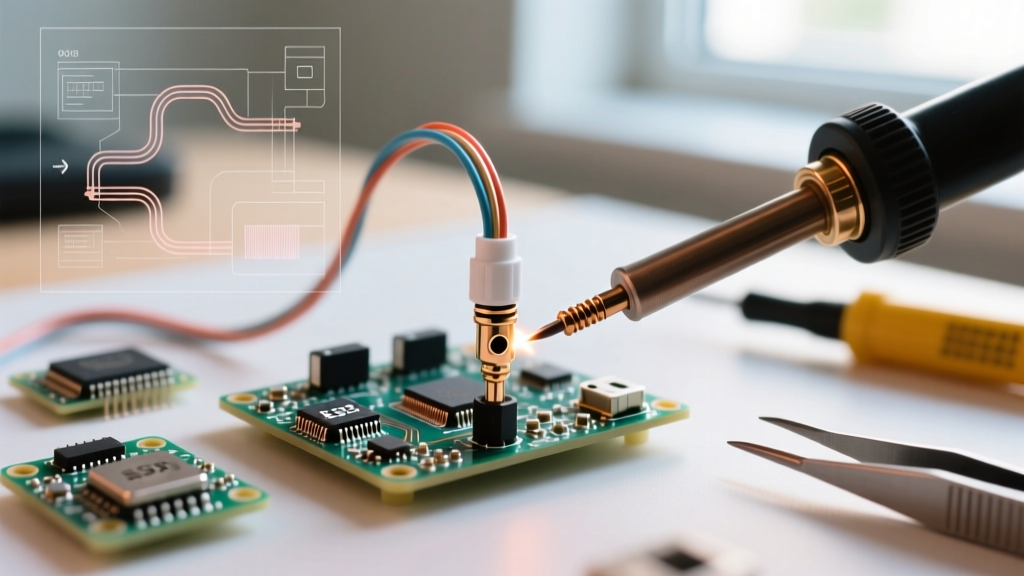
When soldering the tiny signal lugs on a 3.5mm TRRS plug, clamp a metal hemostat or alligator clip onto the lug between the solder cup and the plastic body. The metal jaws will absorb the thermal energy traveling toward the plastic, effectively acting as a heat sink and preventing dielectric melt-down.
The TRRS Pinout Nightmare: CTIA vs. OMTP
If you are soldering a 4-pole TRRS jack (Tip, Ring 1, Ring 2, Sleeve) for a headset with an inline microphone, you must understand the two competing standards. As detailed in Sweetwater's comprehensive guide on TRS vs TRRS, wiring a cable to the wrong standard results in 'hollow' or 'karaoke-like' audio where the center-panned vocals cancel out.
Pinout Comparison
- CTIA Standard (Apple, Android, Modern Consoles): Tip = Left, Ring 1 = Right, Ring 2 = Ground, Sleeve = Microphone.
- OMTP Standard (Older Nokia, Early Sony Ericsson): Tip = Left, Ring 1 = Right, Ring 2 = Microphone, Sleeve = Ground.
Troubleshooting Out-of-Phase Audio: If your freshly soldered headset plays music, but vocals sound distant and echoey, you have likely swapped the Ground and Mic connections. The Left and Right channels are returning their ground signals through the microphone pin, causing phase cancellation. Simply re-solder the Ring 2 and Sleeve wires to match the CTIA standard to resolve this.
Strain Relief: Why Hot Glue Fails
A perfectly soldered headphone jack will still fail in three months if the mechanical strain relief is inadequate. When the cable is yanked, the copper strands inside the insulation act as a lever, snapping the solder joint right at the lug entry point.
Industry-Grade Strain Relief Methods
- Adhesive-Lined Heat Shrink: Forget standard polyolefin. Use dual-wall, adhesive-lined heat shrink (like 3M EPS300). When heated, the inner melamine lining melts and bonds the wire jacket directly to the jack barrel, distributing physical stress away from the solder cups.
- Epoxy Potting: For rugged stage environments, fill the backshell of the 1/4-inch jack with a flexible marine-grade epoxy or 3M Scotch-Weld DP420. This immobilizes the wires entirely.
- Mechanical Clamping: Always ensure the cable gland (the threaded backshell) is tightened securely over the wire's outer PVC jacket, not over the exposed internal signal wires.
Frequently Asked Questions (FAQ)
How do I safely desolder a factory 3.5mm jack from a PCB without lifting the pads?
Factory headphone jacks are often wave-soldered with lead-free alloys and anchored by large mechanical ground tabs. Do not use a standard soldering iron to pry them off. Instead, use a low-temperature desoldering alloy (like Chip Quik SMD291AXL) to lower the melting point of the factory solder. Apply the low-temp alloy to all pins, then use a hot air rework station set to 250°C (482°F) at a low airflow rate (30%) to evenly heat the tabs until the jack lifts out with gentle tweezers pressure.
What wire gauge is best for custom headphone cables?
For internal soldering to the jack lugs, 24 AWG to 26 AWG stranded copper is ideal. Thicker wires (like 20 AWG) are too stiff; their mechanical rigidity will transfer cable movement directly to the solder joint, causing fatigue fractures. High-purity OFC (Oxygen-Free Copper) cables, such as Mogami W2330, offer excellent flexibility and fit perfectly into the micro-cups of Neutrik and Switchcraft plugs.
Why does my solder look dull and grainy on the ground lug?
A dull, grainy appearance indicates a disturbed joint or a cold joint. The large ground lug on 1/4-inch jacks acts as a massive heat sink. If your iron lacks the thermal recovery rate to keep the lug at melting temperature, the solder cools prematurely while crystallizing. Furthermore, if the wire is moved even a fraction of a millimeter while the solder is in its 'pasty' transition phase, the internal crystalline structure fractures, resulting in a high-resistance, noisy connection. Always use a high-wattage iron (60W+) for large ground lugs and hold the wire perfectly still for 3 seconds after removing the iron.
Is flux necessary for headphone jack soldering?
Absolutely. As highlighted in SparkFun's soldering fundamentals, flux removes oxidation and reduces surface tension. For audio jacks, use a no-clean liquid flux (like Kester 951) applied with a precision pen. This allows the solder to wick cleanly into the cup without forming the tiny 'whiskers' that cause short circuits between the tightly packed Tip and Ring lugs on 3.5mm connectors.