
The Metallurgical Reality of Electrical Soldering
Electrical soldering is frequently misunderstood as a simple mechanical glue. In reality, it is a complex metallurgical process where molten alloy dissolves a microscopic layer of the base metal (usually copper) to form an Intermetallic Compound (IMC) layer, primarily Cu6Sn5. A reliable electrical connection depends entirely on the thickness and uniformity of this IMC layer. Too thin, and you get a high-resistance cold joint; too thick (due to excessive heat dwell time), and the joint becomes brittle and prone to mechanical fracture under thermal cycling.
Whether you are prototyping a high-frequency RF board, repairing a 10AWG drone power distribution board, or assembling 0.5mm pitch QFP microcontrollers, applying a one-size-fits-all approach guarantees failure. This decision framework provides a structured methodology for selecting your alloy, thermal delivery system, flux chemistry, and tip geometry based on the specific constraints of your 2026 project.
Phase 1: Alloy Selection Matrix
The transition to RoHS compliance forced the industry toward lead-free alloys, but leaded solder remains legal and superior for prototyping, aerospace, and medical life-support devices due to its lower melting point and superior wetting characteristics. According to the Indium Corporation's solder alloy database, selecting the right alloy dictates your entire thermal profile.
| Alloy Designation | Composition | Melting Point | Best Application | Approx. Cost (2026) |
|---|---|---|---|---|
| Sn63/Pb37 | 63% Tin, 37% Lead | 183°C (Eutectic) | Prototyping, DIY, aerospace, thermal-sensitive components. | $35 - $45 / lb |
| Sn60/Pb40 | 60% Tin, 40% Lead | 183°C - 190°C | General purpose through-hole where slight plastic range is acceptable. | $30 - $40 / lb |
| SAC305 | 96.5% Sn, 3.0% Ag, 0.5% Cu | 217°C - 220°C | Commercial RoHS-compliant SMD assembly, high-reliability consumer tech. | $80 - $110 / lb |
| SN100C | 99.3% Sn, 0.7% Cu, Ni-doped | 227°C | Wave soldering, heavy-duty power electronics, RoHS compliant. | $40 - $55 / lb |
Decision Rule: If you are not legally bound by RoHS (e.g., commercial manufacturing), default to Sn63/Pb37. Its eutectic nature means it transitions instantly from solid to liquid, eliminating the "plastic range" that causes micro-fractures if the joint is disturbed during cooling.
Phase 2: Thermal Delivery & Station Profiling
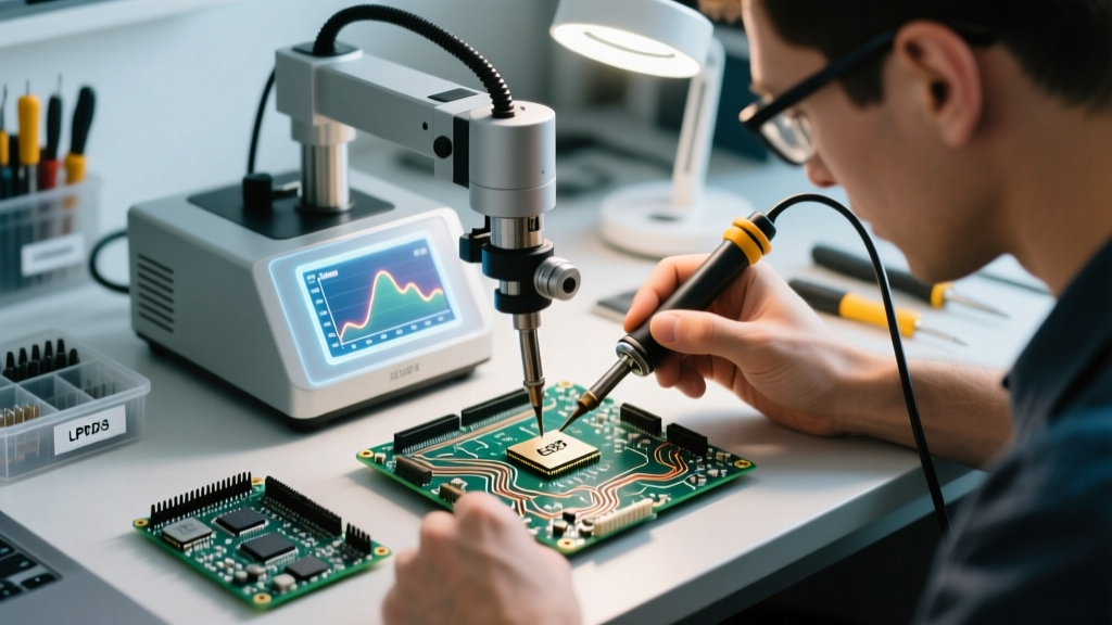
A common novice mistake is equating higher wattage with better performance. Wattage only dictates how fast the heating element can recover thermal energy; thermal mass and tip geometry dictate how efficiently that energy transfers to the pad. A 40W iron with a massive D24 chisel tip will melt a heavy ground plane faster than a 70W iron equipped with a micro-conical I-tip, because the conical tip lacks the physical mass to sustain heat transfer upon contact with the copper.
Station Tiering for 2026
- Entry-Level / Portable (Under $50): The Pinecil V2 (approx. $26) utilizes a RISC-V chip and supports USB-C PD 3.0 up to 65W. It is exceptional for SMD work and field repairs but struggles with heavy thermal recovery on multi-layer boards with large internal ground planes.
- Mid-Tier Benchtop ($100 - $130): The Hakko FX-888D ($115) and Weller WE1010NA ($115) are the industry workhorses. Both offer 70W output and excellent sensor-to-tip proximity. The Hakko T18 tip ecosystem provides massive versatility for under $8 per tip.
- High-Performance / Heavy Thermal ($400+): The JBC CD-2BQF (approx. $450) uses a proprietary cartridge system where the heating element is integrated directly into the tip. This allows 130W stations to recover heat in under 2 seconds, making it mandatory for soldering thick copper pours (e.g., 2oz or 3oz copper on motor controllers).
Phase 3: Flux Chemistry Decision Tree
Flux is arguably more important than the solder itself. It removes copper oxides and prevents re-oxidation during the heating phase. Choosing the wrong flux can lead to parasitic capacitance in high-frequency circuits or electrochemical migration (dendrite growth) causing short circuits.
Industry Standard Note: The IPC-J-STD-001 standard strictly categorizes flux residues and dictates cleaning requirements based on the operating environment of the final assembly. Flux selection must align with your post-soldering cleaning capabilities.
Flux Classification Guide
- Rosin (R) & Mildly Activated Rosin (RMA): The traditional standard (e.g., Kester 186). Leaves a hard, non-conductive residue. Excellent for general DIY and through-hole. RMA contains mild activators for slightly oxidized boards. Cleaning is optional but recommended with isopropyl alcohol (IPA).
- No-Clean (NC): Formulated with low-solid synthetic resins (e.g., Kester 245). The residue is designed to be left on the board. Warning: While electrically safe, NC flux residue can interfere with bed-of-nails testing and conformal coating adhesion. Furthermore, in high-impedance analog circuits, even NC residue can cause leakage currents.
- Water-Soluble (Organic Acid / OA): Highly active fluxes designed for severely oxidized components or automated wave soldering. Decision Rule: Never use OA flux for prototyping or manual PCB repair unless you have an ultrasonic cleaner or heated DI (deionized) water wash station. Residual OA flux will aggressively corrode copper traces and cause dendrite shorts within weeks.
Phase 4: Tip Geometry & Thermal Mass Matching
Match the tip shape to the physical geometry of the connection, not just the size. The goal is to maximize the surface area contact between the tip, the component lead, and the PCB pad simultaneously.
- Chisel (D-Series): The most versatile. The flat face allows you to press against a pad and a lead simultaneously, creating a thermal bridge. Essential for 0805 and 0603 SMD passives.
- Hoof / Micro-Hoof: Features a concave scoop. Ideal for drag-soldering SOIC and TQFP pins, as the molten solder pools in the hoof and surface tension pulls it evenly across the pins without bridging.
- Knife (K-Tip): Combines the edge of a chisel with a pointed tip. The sharp point is used for reworking individual 0.5mm pitch QFP pins, while the flat blade can be used for drag soldering or cleaning excess solder with a wick.
- Conical (B-Series): Often mistakenly bought by beginners. Conical tips have terrible thermal transfer because they only touch the pad at a microscopic point. Avoid them entirely unless doing extremely fine-pitch (0.4mm or less) micro-BGA rework under a microscope.
Real-World Failure Modes and Edge Cases
Even with the correct framework, execution errors occur. Here is how to diagnose and correct the most common electrical soldering failures according to NASA Workmanship Standard 8739.3 and IPC guidelines:
1. Pad Cratering and Lifting
The Cause: Dwell time exceeds 3 to 5 seconds, or excessive mechanical pressure is applied with the iron. The FR4 fiberglass substrate degrades, and the adhesive bonding the copper to the board fails.
The Fix: Increase the iron temperature by 15°C and switch to a tip with higher thermal mass (e.g., move from a 1.6mm chisel to a 2.4mm chisel) to reduce the time required to reach flow temperature. Never press hard; let the flux do the work.
2. Tombstoning (Drawbridging)
The Cause: Uneven heating of a two-terminal SMD component (like a capacitor). One pad reaches reflow temperature before the other, and the surface tension of the molten solder on the heated side pulls the component upright.
The Fix: Apply a small amount of liquid flux to both pads. Pre-tin both pads evenly before placing the component. When reflowing, touch the iron to the component body and both pads simultaneously to ensure equal thermal saturation.
3. Cold Joints with Grainy Appearance
The Cause: The joint was moved during the phase transition from liquid to solid, or the flux was completely exhausted (burned off) before the solder wetted the copper, resulting in oxidation.
The Fix: Do not simply add more solder. Apply fresh liquid or paste flux to the joint to dissolve the oxides, then reheat with a clean, tinned tip until the solder flows smoothly into a shiny, concave fillet.
Summary: Your Pre-Solder Checklist
Before powering on your station, run this mental framework:
- Substrate & Component Sensitivity: Does this dictate a lower melting point (Sn63) or require RoHS (SAC305)?
- Thermal Demand: Am I soldering a 14AWG wire (requires high mass hoof tip, 350°C) or a 0603 resistor (requires standard chisel, 300°C)?
- Flux Activity: Will I be cleaning this board, or do I need a true No-Clean formulation?
By systematically aligning your metallurgy, thermal delivery, and chemistry, you transition from guessing to engineering reliable, long-lasting electrical connections.