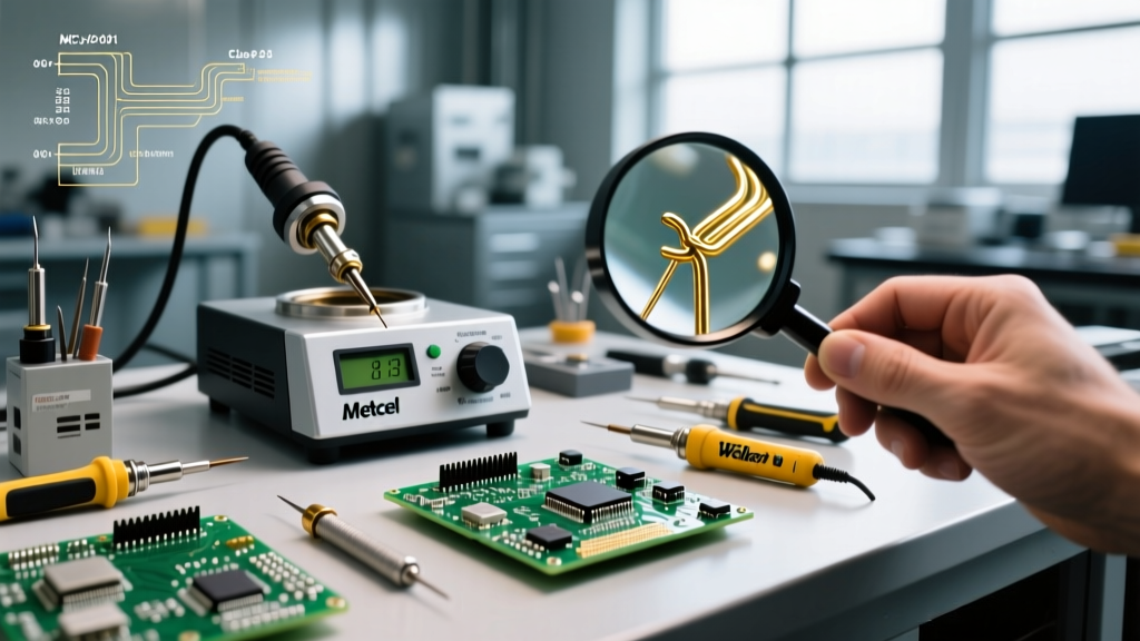

The Stakes of High-Reliability Electronics
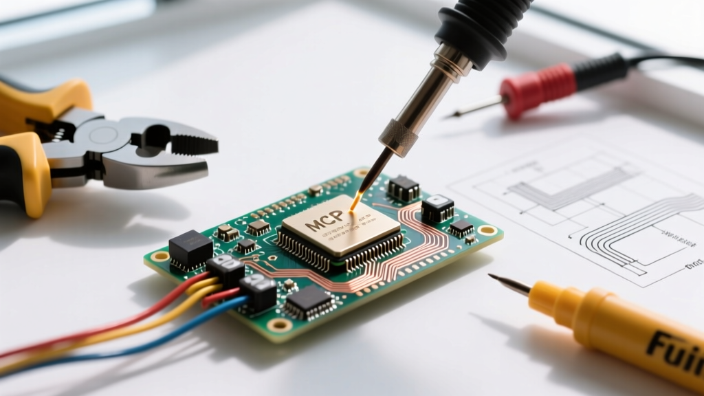
When a consumer smartphone fails, it is an inconvenience. When an avionics control module or a deep-space telemetry board fails, it can result in the loss of a multi-million dollar mission or human life. Aerospace soldering is not merely about joining two metals; it is a highly regulated discipline governed by strict material science, thermal dynamics, and rigorous inspection criteria. As of 2026, with the rapid expansion of low-Earth orbit (LEO) satellite constellations and next-generation reusable launch vehicles, the demand for technicians and engineers certified in high-reliability (Hi-Rel) soldering has reached unprecedented levels.
This comprehensive guide breaks down the exact equipment, materials, and procedural frameworks required to execute aerospace-grade solder joints, specifically focusing on the stringent requirements of IPC Class 3 and the elite Class 3A space addendum.
Decoding the Standards: IPC J-STD-001 and Class 3A
In the commercial electronics world, IPC-A-610 Class 2 (Dedicated Service Electronic Products) is the standard. However, aerospace and military applications demand Class 3 (High-Performance Electronic Products). According to the IPC (Association Connecting Electronics Industries), Class 3 products are those where continued performance on-demand is critical, and downtime cannot be tolerated.
For space applications, the industry relies on the Class 3A Space Addendum. This addendum introduces extreme scrutiny regarding:
- Barrel Fill: Plated through-holes (PTH) must achieve a minimum of 75% vertical solder fill (Class 3 standard), but Class 3A often mandates 100% fill for critical flight hardware.
- Cleanliness: Even 'no-clean' flux residues must be rigorously evaluated for outgassing in vacuum environments. Rosin Mildly Activated (RMA) fluxes are frequently used and must be chemically cleaned post-soldering to prevent ionic contamination.
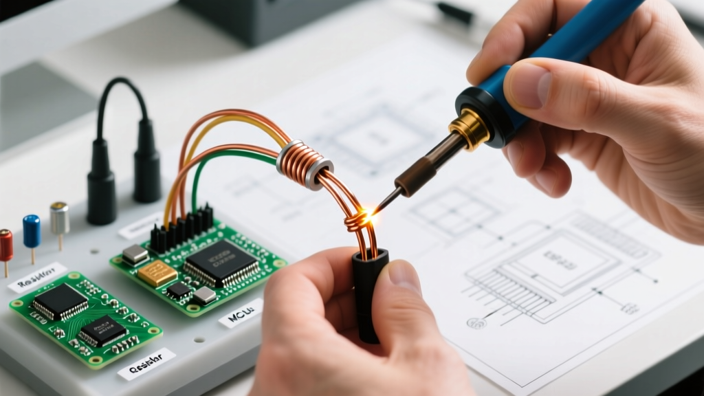
- Wire Preparation: Nicking or scraping of the conductor base metal during stripping is an automatic rejection. Thermal or laser wire stripping is heavily favored over mechanical blades.
Expert Insight: "In aerospace soldering, the joint is only as reliable as the preparation that precedes it. A perfectly wetted joint on a mechanically damaged conductor will fail under the acoustic vibration of a rocket launch." — Senior Hi-Rel Manufacturing Engineer, 2025 Aerospace Manufacturing Symposium.
2026 Aerospace Soldering Equipment Buyer’s Matrix
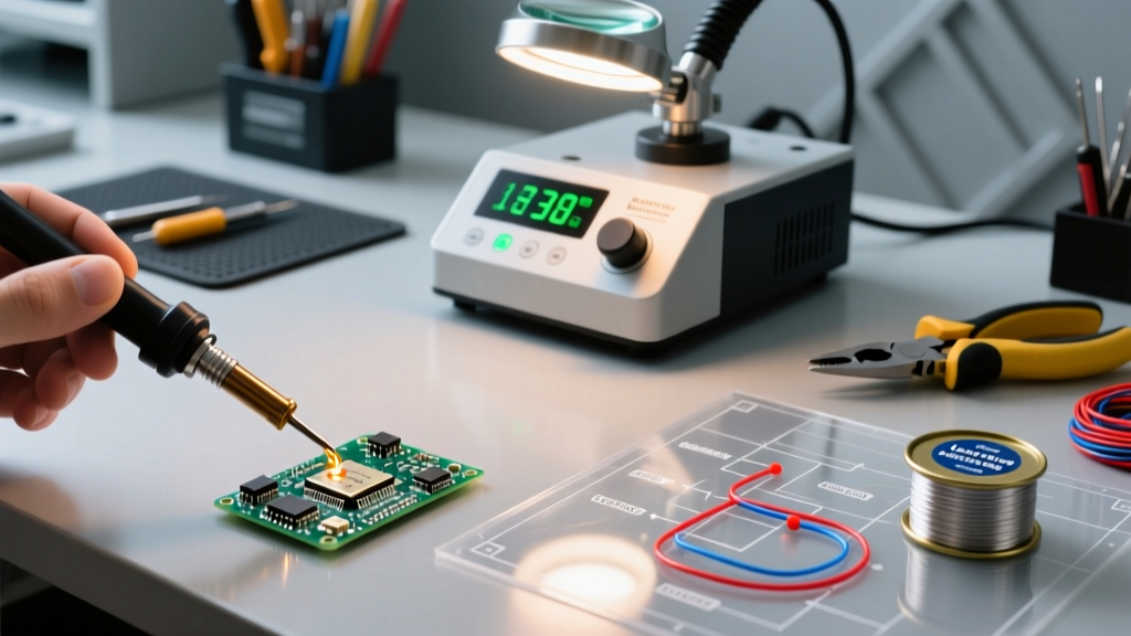
Standard hobbyist or basic commercial soldering stations lack the thermal recovery and precision required for aerospace PCBs, which often feature heavy ground planes that act as massive heat sinks. Below is the benchmark equipment matrix for a compliant aerospace soldering workstation in 2026.
| Equipment Category | Recommended Model (2026) | Approx. Cost | Why It Meets Aerospace Standards |
|---|---|---|---|
| Soldering Station | Metcal MX-5200 SmartHeat | $780 - $850 | Utilizes Curie-point heating technology. The tip stops heating exactly at its designed temperature, eliminating thermal overshoot that can delicate aerospace ICs. |
| Dual-Channel Station | Weller WX2021 with WXP120 | $900 - $1,050 | Exceptional thermal recovery for heavy multi-layer avionics boards; fully traceable and lockable via software for QA compliance. |
| Wire Stripper | Meisei MS-1000 Thermal Stripper | $450 - $520 | Melts insulation without touching the copper conductor, eliminating the risk of mechanical nicking (a strict IPC Class 3 defect). |
| Fume Extraction | Metcal MX-BV5 or Hakko FA-430 | $600 - $750 | HEPA and activated carbon filtration required to maintain cleanroom ISO standards and prevent flux contamination on optical sensors. |
| Inspection Microscope | AmScope 7x-45x Trinocular | $400 - $600 | Class 3 inspection requires 10x to 30x magnification to verify wetting angles, fillet shapes, and micro-cracks in the solder meniscus. |
Material Selection: Alloys, Flux, and the Tin Whisker Threat
One of the most significant divergences between commercial and aerospace soldering is the approach to lead-free (RoHS) compliance. While consumer electronics transitioned to SAC305 (Tin-Silver-Copper) alloys decades ago, the aerospace sector largely retains exemptions for leaded solders.
The Lead-Free Dilemma and Tin Whiskers
Pure tin and high-tin lead-free alloys are susceptible to tin whiskers—microscopic, electrically conductive crystalline structures that grow from the solder joint over time. In the vacuum of space or the high-vibration environment of a jet engine, these whiskers can break off and cause catastrophic short circuits. The NASA NEPP Tin Whisker Database documents numerous mission failures attributed to this phenomenon. Consequently, Sn63Pb37 (Tin 63% / Lead 37%) remains the gold standard for aerospace PTH and critical SMT applications because the addition of lead (even as little as 3%) effectively mitigates whisker growth.
Solder Alloy Comparison for Aerospace Applications
| Alloy Designation | Composition | Melting Point | Whisker Risk | Primary Aerospace Use Case |
|---|---|---|---|---|
| Sn63Pb37 | 63% Sn, 37% Pb | 183°C (Eutectic) | Very Low | Critical flight hardware, avionics, space systems (under RoHS exemption). |
| SAC305 | 96.5% Sn, 3% Ag, 0.5% Cu | 217°C - 220°C | High | Commercial launch vehicle non-critical systems, ground support equipment (GSE). |
| Sn96.3Ag3.0Cu0.7 | Modified SAC | 218°C | High | High-temp environments where lead is strictly prohibited by specific agency mandates. |
| Indalloy #281 | Sn, Ag, Cu, Ni, Ge | 217°C | Moderate | Specialized lead-free wave soldering where dross reduction is required. |
Step-by-Step: Executing a Class 3 Plated Through-Hole (PTH) Joint
Achieving a compliant Class 3 PTH joint requires meticulous attention to thermal profiles and dwell times. Follow this procedure for a standard 20 AWG solid wire into a multi-layer avionics board:
- Preparation & Tinning: Thermally strip the wire to expose exactly the length required for the pin protrusion (typically 1.5mm to 2.0mm past the board surface). Pre-tin the wire using a fluxed solder pot or iron, ensuring the tinning stops 0.5mm before the insulation to prevent wicking under the jacket.
- Insertion: Insert the component lead or wire. The bend radius must not stress the component body. Secure the lead mechanically if required before soldering.
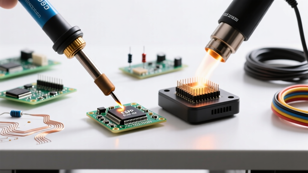
- Thermal Pre-Heat: If the board has heavy internal copper planes, use a bottom-side IR pre-heater set to 100°C - 120°C to reduce the thermal delta and prevent pad lifting.
- Flux Application: Apply a controlled drop of RMA liquid flux to the barrel. Do not use aerosol sprays, which can contaminate adjacent test points or optical surfaces.
- Solder Application: Apply the Metcal SmartHeat tip to the pad and the lead simultaneously. Introduce the Sn63Pb37 solder wire to the joint, not the iron tip. Target a tip temperature of 320°C - 350°C.
- Dwell Time & Capillary Action: Allow the solder to flow via capillary action into the barrel. The ideal dwell time is 1.5 to 3.0 seconds. Prolonged heating degrades the flux and risks dissolving the board's copper plating.
- Cooling: Remove the heat and hold the assembly perfectly still. A disturbed joint during the plastic (cooling) phase will result in a frosty, granular appearance—an automatic Class 3 rejection.
Common Failure Modes and Inspection Criteria
Even with premium equipment, aerospace solder joints can fail if the operator lacks an understanding of metallurgical failure modes. According to data compiled by the NASA Electronic Parts and Packaging (NEPP) Program, the following are the most common defects flagged during X-ray and microscopic inspection:
1. Disturbed Joints
Characterized by a dull, frosty, or grainy appearance. This occurs when the component or wire moves while the solder is transitioning from a liquid to a solid state. In aerospace vibration profiles, disturbed joints act as stress concentrators and will rapidly propagate micro-cracks.
2. Insufficient Wetting (Non-Wetting)
The solder balls up on the pad or lead rather than forming a smooth, concave fillet. This is usually caused by oxidized pads, expired flux, or insufficient thermal transfer. The contact angle must be less than 90 degrees for Class 3 acceptance.
3. Solder Wicking
When solder flows too far up the wire lead, away from the PCB pad. This leaves a rigid, brittle section of wire that is highly susceptible to snapping under mechanical shock. Wicking is prevented by proper heat management and avoiding over-tinning prior to insertion.
4. Outgassing and Voiding
In vacuum environments, trapped flux volatiles can expand, creating voids within the solder barrel or blowing out the solder entirely (solder spatter). This is why aerospace manufacturers mandate strict flux baking or vacuum-compatible no-clean chemistries.
Frequently Asked Questions (FAQ)
Can I use standard commercial no-clean flux for aerospace soldering?
Generally, no. While commercial no-clean fluxes are safe for consumer electronics, the residues can outgas in a vacuum, potentially contaminating sensitive optical sensors or star trackers on satellites. If no-clean must be used, it requires rigorous qualification testing per ASTM E595 for total mass loss (TML) and collected volatile condensable materials (CVCM).
Why is Sn63Pb37 preferred over SAC305 for space hardware?
SAC305 (lead-free) is prone to tin whisker growth, which can cause short circuits in high-density, high-voltage aerospace circuitry. Furthermore, Sn63Pb37 is eutectic (melts and freezes at the exact same temperature, 183°C), eliminating the plastic phase and reducing the risk of disturbed joints during cooling.
What magnification is required to inspect a Class 3A solder joint?
IPC standards typically require 3x to 10x magnification for general inspection, but Class 3A and specific space addendums frequently mandate 10x to 30x for critical connections, especially when inspecting for micro-cracks, pad lifting, and precise fillet wetting angles on micro-BGA or fine-pitch SMT components.
Conclusion: Investing in Reliability
Aerospace soldering is an investment in certainty. By equipping your workstation with Curie-point temperature-controlled stations, thermal wire strippers, and high-resolution optics, you eliminate the variables that lead to catastrophic field failures. Adhering strictly to IPC J-STD-001 Class 3 and NASA workmanship standards ensures that when your hardware is subjected to the violent acoustic shock of a launch or the extreme thermal cycling of orbit, every single joint holds fast.