
The Critical Role of Copper in Electronics Soldering
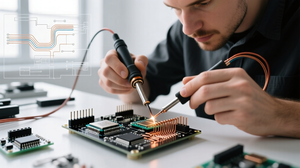
Copper is the undisputed backbone of electrical and electronics DIY. Its exceptional thermal conductivity (approximately 401 W/m·K) and electrical conductivity make it the primary material for both the wires we connect and the soldering iron tips we use to melt alloys. However, as the hobbyist and professional markets have aggressively shifted toward lead-free alloys like SAC305 in 2026, the thermal and chemical stresses placed on copper components have increased significantly. Selecting the right copper for soldering—whether you are choosing wire for a custom wiring harness or evaluating the metallurgy of your soldering tip—requires a deep understanding of material properties, insulation types, and preparation techniques.
This comprehensive guide breaks down the exact specifications, pricing, and failure modes associated with copper wire and copper-core soldering tips, providing actionable frameworks for your next build.
Copper Wire Selection: Solid vs. Stranded & Insulation Types
When buying copper wire for PCBs, breadboards, or harnesses, the physical construction and insulation material dictate your soldering success. The two primary decisions are the stranding (solid vs. stranded) and the jacket material (PVC vs. Silicone).
Solid vs. Stranded Copper
Solid copper wire consists of a single, rigid conductor. It is ideal for inserting into breadboards, wrapping around terminal posts, and soldering directly to large PCB through-holes. However, it suffers from metal fatigue and will snap if subjected to repeated bending.
Stranded copper wire is composed of multiple thinner copper filaments twisted together. It offers superior flexibility and vibration resistance, making it mandatory for moving parts, drone ESC connections, and RC models. The trade-off is that stranded wire has a higher surface area, which oxidizes faster and requires careful tinning to prevent fraying during soldering.
| Wire Type | Best Use Case | Flex Life | Solderability | Avg Price (100ft, 22 AWG) |
|---|---|---|---|---|
| Solid Bare | PCB jumpers, breadboards | Low | Moderate (prone to oxidation) | $8 - $12 |
| Solid Tinned | Through-hole components | Low | Excellent | $14 - $18 |
| Stranded PVC | General chassis wiring | Medium | Good (insulation melts back) | $12 - $16 |
| Stranded Silicone | High-temp, high-flex harnesses | High | Excellent | $22 - $35 |
The Insulation Factor: Why Silicone Dominates in 2026
Historically, PVC (Polyvinyl Chloride) was the standard wire insulation. However, when a 350°C soldering iron touches PVC, the insulation rapidly melts and shrinks back, exposing bare copper and creating short-circuit risks. Silicone-insulated tinned copper wire (such as the popular Belden or generic 30AWG-10AWG silicone lines found on major marketplaces) can withstand temperatures up to 200°C continuously and brief spikes over 300°C without melting. For any DIY soldering project involving high-wattage components or lead-free solder, silicone is the mandatory choice.
AWG Sizing Cheat Sheet for DIY Electronics
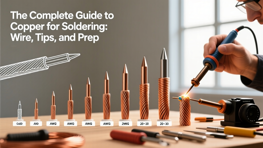
Choosing the correct American Wire Gauge (AWG) prevents voltage drop and overheating. According to the Engineering Toolbox AWG charts, the current-carrying capacity of copper drops significantly as the gauge number increases. Here is a practical sizing framework for common DIY scenarios:
- 30-28 AWG: SMD jumper wires, micro-sensor repairs, and delicate PCB trace fixes. (Max current: ~1.4A for 28 AWG).
- 24-22 AWG: Standard breadboarding, Arduino/Raspberry Pi GPIO connections, and low-power LED strips. (Max current: ~7A for 22 AWG).
- 18-16 AWG: Power distribution on custom PCBs, 3D printer heater cartridges, and standard DC barrel jack wiring. (Max current: ~16A for 16 AWG).
- 12-10 AWG: High-current LiPo battery leads, main power feeds for robotics, and automotive DIY. (Max current: ~40A for 10 AWG).
The Truth About Copper Soldering Iron Tips
A common misconception among beginners is that soldering iron tips are made of pure copper. While copper is the core material due to its rapid heat transfer, a pure copper tip would be destroyed in a matter of hours. Molten solder (especially tin-heavy alloys like Sn63/Pb37 or SAC305) actively dissolves copper in a process known as copper leaching or solder erosion.
Modern Tip Metallurgy
As detailed in the Hakko USA metallurgy guide, modern high-performance tips (like the Hakko T18 series or Weller RT series) feature a multi-layer construction:
- Tellurium Copper Core: Provides rapid thermal recovery from the heating element to the working face.
- Iron Plating (100-150 µm): A critical barrier that prevents the molten solder from dissolving the copper core.
- Chromium/Nickel Layer: Applied to the non-working areas of the tip to prevent solder from creeping up the shaft.
- Tin Pre-coating: A factory-applied layer to prevent oxidation during storage.
Expert Warning: Never file or sand a modern soldering tip to remove oxidation. Doing so will breach the microscopic iron plating, exposing the copper core. Once exposed, the tip will pit, hollow out, and become completely unusable within a single soldering session.
Step-by-Step: Prepping and Tinning Stranded Copper Wire
Proper preparation of stranded copper wire is mandated by professional standards like NASA-STD-8739.3 for workmanship. Failing to tin stranded wire results in 'birdcaging' (fraying), which causes stray strands to bridge adjacent pads and create catastrophic short circuits.
The 4-Step Tinning Protocol
- Strip with Precision: Use a calibrated wire stripper (e.g., Hakko CHP or Engineer PA-09) to remove exactly 1/8 to 1/4 inch of insulation. Ensure no copper filaments are nicked or cut.
- Twist at a 14-Degree Angle: Gently twist the exposed strands in the direction of the natural lay (usually clockwise) at a tight 14 to 16-degree angle. Do not over-twist, which can work-harden and snap the copper.
- Apply Flux: Dip the twisted tip into a rosin-based flux (like MG Chemicals 8341) or apply a dab of tacky flux (Amtech NC-559). Never rely solely on the rosin core inside your solder wire for initial tinning.
- Heat and Feed: Set your iron to 320°C (for leaded) or 350°C (for lead-free). Touch the iron tip to the copper wire (not the solder) for 1 second to transfer heat, then feed the solder into the wire opposite the iron. Capillary action will draw the solder through the strands. Remove heat immediately once the solder wicks to the base of the insulation.
Common Failure Modes When Soldering Copper
Even experienced DIYers encounter specific failure modes when working with copper materials. Recognizing these edge cases will save you hours of troubleshooting.
- Solder Wicking: If you apply heat for too long, solder will wick up the stranded wire and under the insulation. This creates a rigid, brittle section of wire right at the stress relief point, which will eventually snap under mechanical vibration. Fix: Limit heat application to 2-3 seconds and use a heat sink clamp.
- Cold Joints on Oxidized Copper: Bare copper wire left exposed to humid air develops cupric oxide, which solder will not adhere to, resulting in a dull, grainy cold joint. Fix: Always use an active flux or mechanically abrade the wire with fine brass wool before soldering.
- Tip De-wetting: When the iron plating on a copper-core tip becomes oxidized (often from leaving the iron at 400°C while idle), solder will ball up and roll off. Fix: Use a damp cellulose sponge or brass wire tip tinner (like Hakko 599B) and re-tin immediately with 63/37 solder, which has a lower melting point and higher wetting action.
Frequently Asked Questions
Can I use plumbing copper pipe solder for electronics?
No. Plumbing solder (often 95/5 tin-antimony or 50/50 tin-lead) uses highly corrosive acid-core fluxes designed to eat through heavy copper oxidation on pipes. If used on electronics, the acid residue will rapidly corrode your PCB traces and copper component leads, leading to catastrophic failure. Always use rosin-core (RMA) or no-clean flux solder for electronics.
Why does my tinned copper wire look dull and gray?
A dull, gray, or frosty appearance on tinned copper wire usually indicates a cold joint, oxidation during the cooling phase, or the use of lead-free solder (which naturally dries with a matte finish compared to the shiny finish of Sn63/Pb37). If the joint is mechanically solid, the matte finish of lead-free SAC alloys is normal and acceptable.