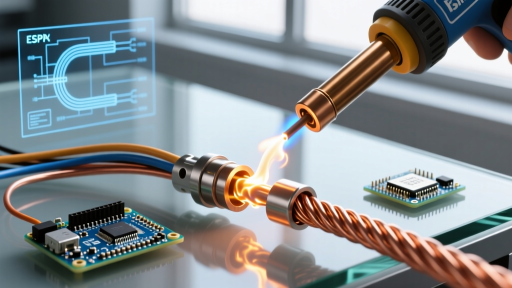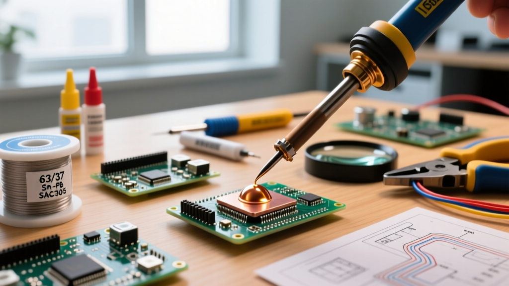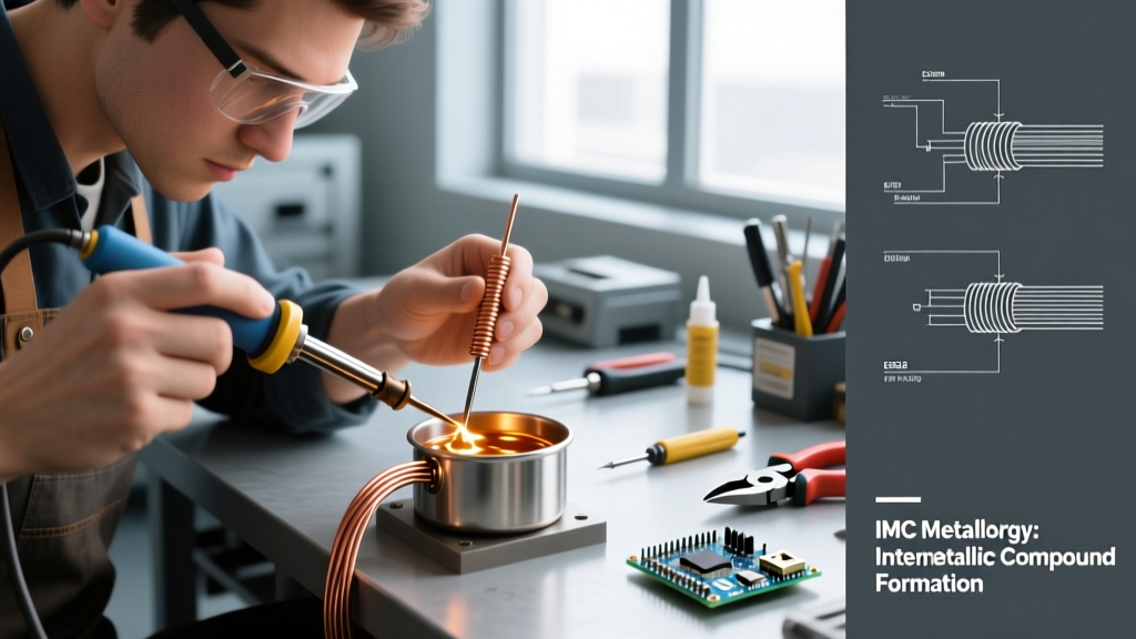

Most hobbyists and beginners define soldering simply as 'melting metal to stick things together.' However, in professional electronics manufacturing, aerospace wiring, and high-reliability DIY projects, the definition of soldering is rooted in complex metallurgy and thermodynamics. It is not a mechanical fastening process like gluing or crimping; it is a metallurgical diffusion process. Understanding this true definition is the first step in troubleshooting faulty connections, selecting the right alloys, and achieving IPC-compliant joints.
In this comprehensive FAQ and troubleshooting guide, we move beyond the dictionary definition of soldering to explore the microstructural realities of the intermetallic compound (IMC) layer, decode flux classifications, and provide actionable solutions for common joint failures.
The Metallurgical Definition of Soldering
Technically speaking, soldering is defined as a joining process where two or more base metals are bonded together by melting and flowing a filler metal (solder) into the joint via capillary action, at temperatures below the melting point of the base metals. The critical differentiator between a true solder joint and a simple mechanical wrap is the formation of an Intermetallic Compound (IMC).
When molten SAC305 (Sn96.5/Ag3.0/Cu0.5) solder at 250°C contacts a copper PCB pad, the tin (Sn) in the solder reacts with the copper (Cu) to form a distinct crystalline layer—primarily Cu6Sn5 (eta phase) and, over time or with excessive heat, Cu3Sn (epsilon phase). According to materials science research referenced by TWI Global, this IMC layer is the actual 'glue' of the joint. Without it, you do not have a soldered connection; you merely have solder resting on top of copper.
Expert Insight: A healthy IMC layer should be between 1 to 3 microns thick. If the layer exceeds 5 microns due to excessive dwell time or rework, the joint becomes highly brittle and prone to thermal shock fracturing.
Soldering vs. Brazing vs. Welding: A Metallurgical Matrix
To fully grasp the definition of soldering, it helps to contrast it with adjacent thermal joining methods. The primary dividing line is the liquidus temperature of the filler metal and whether the base metal melts.
| Process | Filler Metal Melting Point | Base Metal Melting | Joint Mechanism | Capillary Action? |
|---|---|---|---|---|
| Soldering | Below 450°C (842°F) | No | IMC Formation & Wetting | Yes (Primary) |
| Brazing | Above 450°C (842°F) | No | Metallurgical Diffusion | Yes (Primary) |
| Welding | N/A (Base metal melts) | Yes | Fusion & Solidification | No |
Troubleshooting the Definition: When the Bond Fails
When a joint fails to meet the metallurgical definition of soldering, it manifests in specific visual and microstructural faults. Here is how to troubleshoot the most common deviations.
1. Non-Wetting vs. Dewetting
- Non-Wetting: The solder fails to adhere to the base metal. The contact angle is greater than 90 degrees. Cause: Heavy oxidation on the pad, incompatible base metals (e.g., trying to solder aluminum with standard rosin flux), or insufficient flux activity.
- Dewetting: The solder initially wets the surface (contact angle < 90 degrees) but then retracts into islands or beads, exposing the base metal. Cause: Contamination (silicone, oils) on the board, or the dissolution of the underlying metallization (e.g., gold or thin tin plating) into the solder bath, leaving a non-solderable barrier layer.
2. Cold Joints vs. Disturbed Joints
These two faults are frequently confused but have entirely different root causes based on the thermal profile.
- Cold Joint: The solder never reached the temperature required to form the IMC layer. The surface appears dull, grainy, and bulbous. Troubleshooting: Increase iron tip temperature by 15°C-20°C, use a larger chisel tip to increase thermal mass transfer, or apply flux to lower the surface tension.
- Disturbed Joint: The IMC layer formed correctly, but the joint was physically moved while the solder was in its 'plastic' state (the phase between liquidus and solidus in non-eutectic alloys). The surface looks cracked or frosted. Troubleshooting: Secure the wires or components mechanically before applying heat. If using SAC305, ensure the cooling profile is rapid enough to pass through the plastic phase quickly.
Defining Flux: The IPC J-STD-004 Classification
You cannot define soldering without defining flux. Flux is the chemical agent that removes oxidation, allowing the metallurgical bond to form. Under IPC Standards (specifically J-STD-004), fluxes are defined by their chemical composition and activity level. Understanding this matrix is vital for troubleshooting corrosion-related failures post-soldering.
- RO (Rosin): Derived from pine trees. Excellent for general electronics. Leaves a benign residue.
- RE (Resin): Synthetic rosin. Better thermal stability for multi-layer boards.
- OR (Organic): Water-soluble acids. Highly active, but must be cleaned post-soldering to prevent dendritic growth and short circuits.
- IN (Inorganic): Contains strong acids (hydrochloric). Used for plumbing and heavy chassis work. Never use on PCBs.
The letters are followed by an activity level (L = Low, M = Moderate, H = High) and a number indicating halide content (0 = no halides, 1 = contains halides). For example, ROL0 (Rosin, Low activity, 0 halides) is the industry standard for no-clean electronics assembly, while ORH1 is used for heavily oxidized plumbing where aggressive cleaning will follow.
FAQ: Common Questions on Soldering Definitions and Standards
Q: What is the definition of a 'eutectic' solder alloy?
A eutectic alloy is a specific mixture of metals that melts and freezes at a single, exact temperature, with no 'plastic' (semi-solid) phase. The classic example is Sn63Pb37 (63% Tin, 37% Lead), which melts sharply at 183°C. Eutectic alloys are preferred for hand soldering because they eliminate the risk of disturbed joints during cooling. Modern lead-free alternatives like SAC305 are near-eutectic, melting between 217°C and 220°C.
Q: How does the IPC define a 'properly filleted' through-hole joint?
According to Kester and IPC-A-610 guidelines, a Class 3 (high-reliability) through-hole solder joint requires 100% barrel fill and a continuous, concave fillet that wets the entire circumference of the lead and the pad. The contact angle must be less than 90 degrees, and the wire outline should be slightly visible through the solder meniscus, proving adequate capillary flow.
Q: Is soldering considered a chemical or physical change?
It is both, which is why the definition of soldering is so unique. The melting and solidification of the solder alloy is a physical change (phase transition). However, the formation of the Intermetallic Compound (IMC) layer at the boundary of the solder and the copper pad is a chemical reaction resulting in a new crystalline structure (Cu6Sn5).
Q: What is the definition of 'tombstoning' in SMD soldering?
Tombstoning (or drawbridging) is a surface-mount defect where a passive component stands vertically on one end, resembling a tombstone. It is caused by unequal wetting forces on the two pads. If the solder on one pad melts and achieves surface tension equilibrium before the other pad, it pulls the component upright. Troubleshooting requires adjusting the stencil aperture to balance solder volume or modifying the reflow oven profile to ensure simultaneous melting.
Final Thoughts on Mastering the Solder Joint
Mastering soldering requires moving past the rudimentary definition of 'melting metal' and embracing the realities of metallurgy, thermal mass, and chemical flux reactions. Whether you are selecting an ROL0 no-clean flux for a delicate 0402 SMD rework or choosing a high-activity organic flux for oxidized 12 AWG automotive wiring, your success depends on facilitating that critical 1-to-3-micron intermetallic bond. By understanding the exact definitions of wetting, dewetting, and eutectic transitions, you can systematically troubleshoot any joint failure that crosses your workbench.