
The Diagnostic Power of Soldering Photography
In modern electronics manufacturing and high-end DIY repair, a simple visual check is rarely enough. Capturing and analyzing a high-resolution picture of soldering work is a critical quality assurance (QA) step. Whether you are documenting a repair for a client, submitting a failure analysis report, or performing remote IPC-A-610 compliance checks, the photograph serves as forensic evidence. A poorly lit, out-of-focus image can mask catastrophic defects like micro-cracks, disturbed joints, or insufficient wetting. Conversely, a properly captured picture of soldering reveals the metallurgical truth of the connection.
This comprehensive guide details the exact optical setups, lighting temperatures, and analytical frameworks required to capture and interpret solder joints according to stringent industry standards, including IPC-A-610 Rev H and NASA-STD-8739.3 workmanship requirements.
Essential Gear for Capturing the Perfect Picture
The most common mistake technicians make when taking a picture of soldering is relying on standard overhead room lighting or the built-in flash of a smartphone. This creates specular highlights (glare) on glossy flux residue and casts harsh shadows that obscure the critical fillet angle. To capture a diagnostically useful image, you must control the color temperature and polarization of your light source.
Optical and Lighting Specifications
| Equipment Category | Recommended Specification | Estimated Cost (2026) | Purpose in Solder Inspection |
|---|---|---|---|
| Light Source | 5500K - 6500K LED Ring Light (CRI 95+) | $45 - $85 | Simulates daylight; prevents warm light from masking dull cold joints. |
| Polarization | Linear Polarizing Film (Cross-Polarized) | $15 - $25 | Eliminates glare from glossy rosin flux and shiny solder surfaces. |
| Optics / Camera | Digital Microscope (e.g., AmScope SE400-Z) or 1:1 Macro Lens | $130 - $450 | Provides 10x-40x magnification to inspect grain structure and micro-fissures. |
| Background | Matte Black or ESD-Safe Silicone Mat | $20 - $40 | Provides high contrast for edge-detection of the solder meniscus. |
Expert Insight: Never use warm lighting (3000K-4000K) when photographing solder joints. Warm light artificially enhances the yellow/red spectrum, making oxidized, grainy cold joints appear shiny and acceptable in the final picture of soldering. Always stick to 5500K+ daylight-balanced LEDs.
Decoding the Image: IPC-A-610 Visual Criteria
Once you have captured a clear, well-lit picture of soldering, the next step is analysis. According to IPC standards, a solder joint must be evaluated on three primary visual axes: wetting, fillet shape, and surface texture. When reviewing your image, zoom in to at least 10x magnification and check for the following criteria.
1. Wetting Angle and Meniscus Visibility
Wetting refers to the ability of the molten solder to adhere to the base metals (the component lead and the PCB pad). In a high-quality picture of soldering, the solder should form a smooth, concave fillet.
- Ideal (Class 3): The wetting angle is less than 45 degrees, blending smoothly into the pad and lead.
- Acceptable (Class 2): The wetting angle is less than 90 degrees, with clear evidence of solder flowing up the component lead.
- Defect (Non-Wetting): The solder beads up like water on a waxed car, forming a convex angle greater than 90 degrees. This indicates oxidized pads or insufficient flux activation.
2. Surface Texture: Shiny vs. Dull
Historically, a shiny joint was considered good, and a dull joint was deemed a 'cold joint.' However, this rule is highly dependent on the alloy used, a nuance often missed by novice inspectors analyzing a picture of soldering.
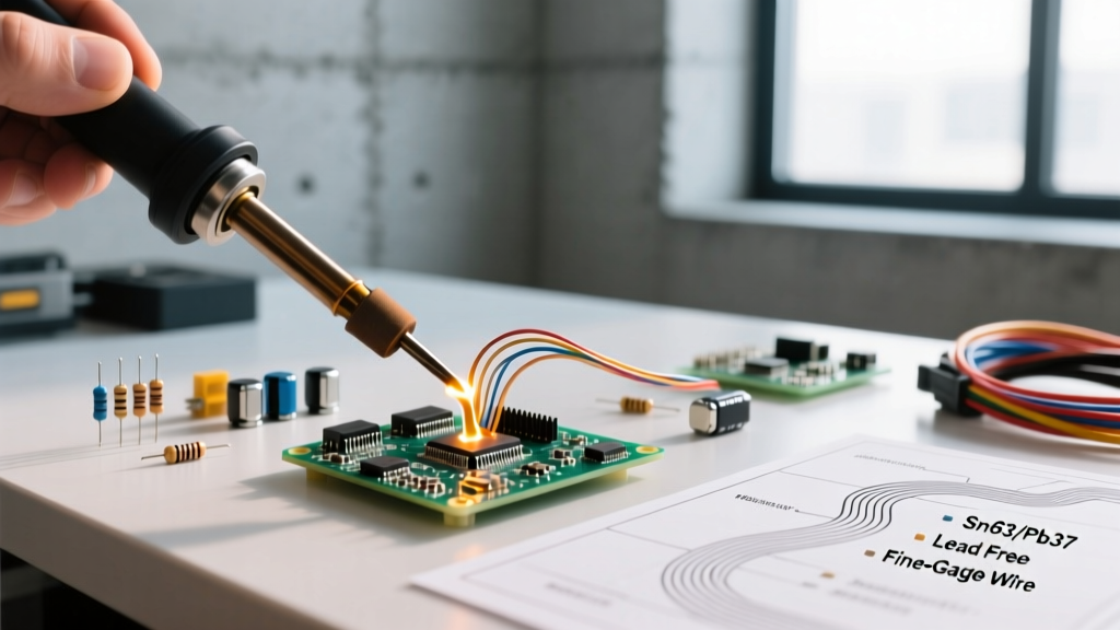
- Sn63/Pb37 (Leaded Eutectic): Should appear bright, shiny, and smooth. A dull or grainy appearance in a leaded joint is a definitive indicator of a disturbed joint (the PCB moved while the solder was in the plastic/mushy state between 183°C and room temperature).
- SAC305 / SAC405 (Lead-Free): Naturally cures with a dull, matte, or slightly grainy finish due to the higher melting point (217°C - 220°C) and different crystallization structure. A perfectly good lead-free joint will look 'bad' to an inspector only familiar with leaded solder.
3. Identifying Solder Bridges and Tombstoning
When inspecting fine-pitch SMD components (0402 or 0201 packages), a macro picture of soldering is mandatory. Look for solder bridges (shorts between adjacent pins), which often appear as a continuous, shiny web of solder hidden beneath flux residue. Tombstoning occurs when one end of a surface-mount capacitor or resistor lifts off the pad, standing vertically. This is caused by uneven heating or unequal paste volume during reflow, creating asymmetric surface tension.
Step-by-Step QA Workflow for Solder Photography
To standardize your inspection process, follow this exact workflow when capturing and evaluating solder joints for QA documentation:
- Clean the Board: Use 99% isopropyl alcohol (IPA) and a lint-free swab to remove excess flux. Residual flux can mask micro-cracks and non-wetting defects.
- Set the Lighting: Position your 5500K ring light at a 30-degree off-axis angle. This raking light casts micro-shadows that highlight the physical topography of the fillet.
- Apply Cross-Polarization: If the joint is still obscured by glossy reflections, place a polarizing filter over the lens and a second over the light source, rotating until the glare vanishes.
- Capture Multiple Angles: Take one top-down picture of soldering, and two 45-degree oblique shots. The oblique shots are critical for verifying the concave shape of the meniscus.
- Annotate and Archive: Use software to draw a tangent line across the fillet to measure the wetting angle digitally before saving the image to your QA database.
Common Visual Anomalies That Aren't Actually Defects
When reviewing a picture of soldering, inspectors frequently flag false positives. Understanding these anomalies saves time and prevents unnecessary rework.
- Flux Carbonization: Dark, blackened rings around a joint often look like burned components. In reality, this is just rosin flux that has been exposed to high heat. If the solder fillet beneath it is smooth and well-wetted, the joint is mechanically sound.
- Solder Wick Dimpling: When desoldering a component, the remaining pad may show small dimples or a slightly rough texture from the copper braid. As long as the copper pad is not lifted or delaminated from the FR4 substrate, it is acceptable for re-soldering.
- Lead Protrusion: In through-hole technology, component leads extending slightly past the solder fillet are normal. IPC-A-610 allows for lead protrusion as long as it does not violate minimum electrical clearance requirements (typically 0.5mm to 1.0mm depending on voltage).
Frequently Asked Questions
Can I use a smartphone to take a diagnostic picture of soldering?
Modern smartphones with dedicated macro lenses (like the 3x or 5x macro sensors on flagship models) can capture adequate images for basic documentation. However, they struggle with depth of field and dynamic range. For formal IPC defect analysis or failure reporting, a dedicated digital microscope or a DSLR with a true 1:1 macro lens is required to resolve micro-fissures and grain boundaries.
Why does my lead-free solder look cracked in the picture?
Lead-free alloys like SAC305 are prone to a phenomenon called 'grainy surface' or 'orange peel' effect. Under high magnification, the crystalline structure of the cooling lead-free solder can resemble a network of fine cracks. Unless the fissure physically penetrates the fillet down to the pad interface (a true thermal fatigue crack), this surface texture is a normal metallurgical characteristic of lead-free reflow and is considered acceptable.
What is the best magnification for inspecting 0402 components?
For 0402 components (which measure just 1.0mm x 0.5mm), a magnification of 20x to 30x is optimal. This provides enough field of view to see the entire component and both pads simultaneously, allowing you to verify that the solder fillet is symmetrical and that no micro-bridging has occurred beneath the component body.