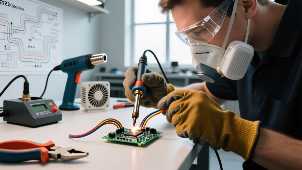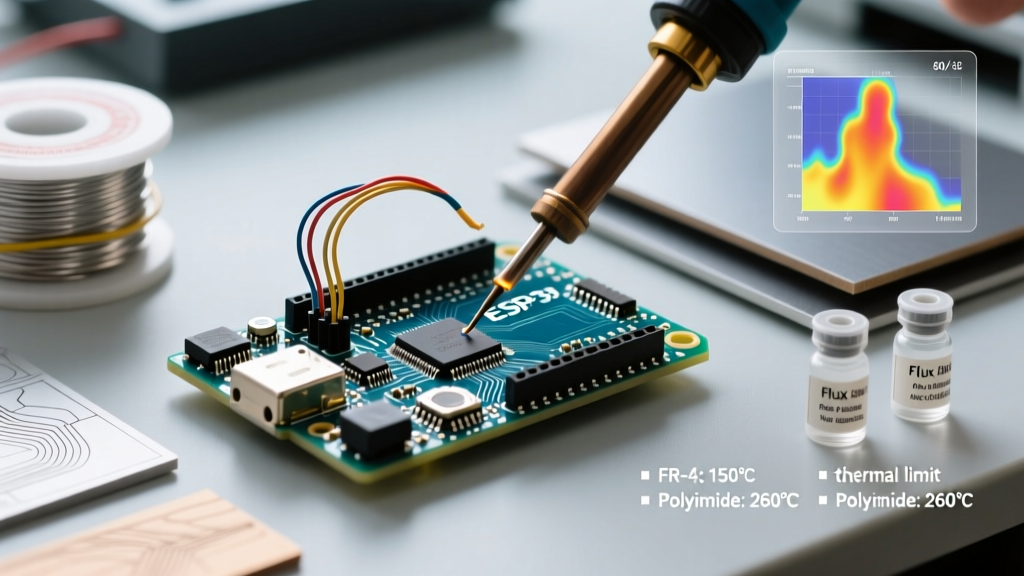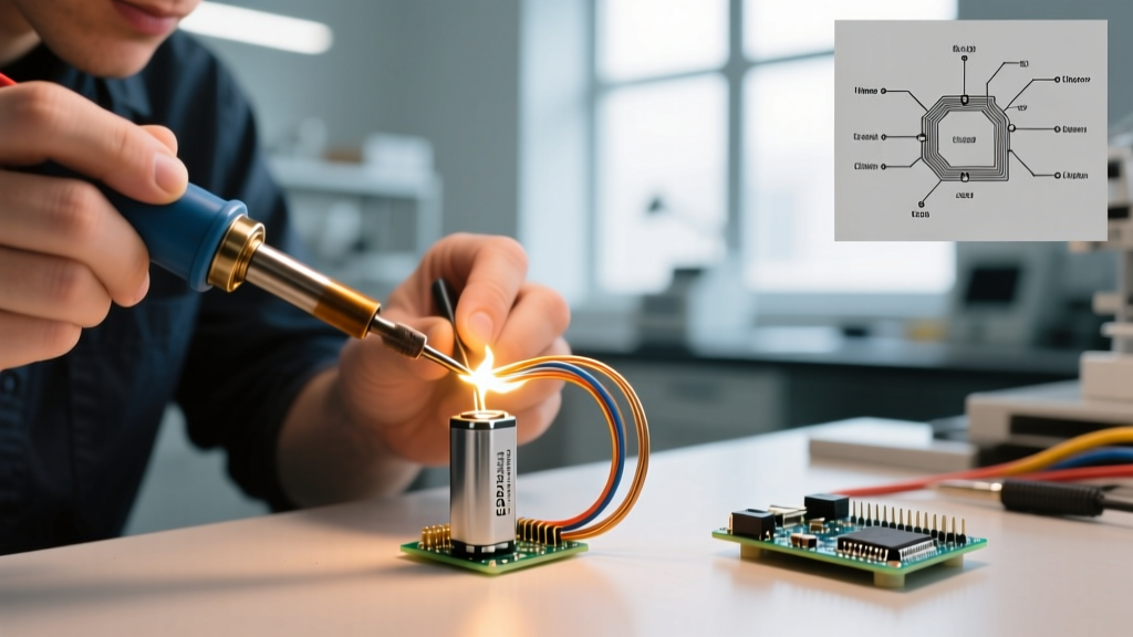

The Core Challenge: Heat vs. Battery Chemistry
Soldering directly to lithium-ion cells (such as 18650, 21700, and LiPo pouch cells) is a high-stakes balancing act. The primary adversary is thermal transfer. Inside a standard cylindrical lithium-ion cell, the polyethylene (PE) separator begins to shut down and shrink at approximately 130°C (266°F). If the internal temperature breaches 160°C (320°F), the separator melts, causing an internal short circuit and triggering catastrophic thermal runaway. According to OSHA guidelines on lithium-ion battery safety, thermal abuse is one of the leading causes of battery venting and fires in assembly environments.
To mitigate this, professional battery pack builders in 2026 rely on high-thermal-mass soldering stations, eutectic solder alloys, and strict dwell-time limits. This guide addresses the most frequent troubleshooting scenarios and FAQs encountered when hand-soldering battery terminals, ensuring your connections are both electrically robust and chemically safe.
Essential Gear for Battery Soldering
Using a generic 60W pencil iron will almost guarantee damaged cells. You need a station that can recover heat instantly when the cold steel can of the battery acts as a massive heat sink. Below is a comparison of modern stations suited for battery tab soldering.
| Soldering Station | Wattage / Recovery | Recommended Tip | Best Use Case |
|---|---|---|---|
| Hakko FX-951 | 70W / Instantaneous | T12-D24 (Chisel) | High-volume 18650/21700 pack building |
| Pinecil V2 (2026 Firmware) | 65W (via USB-C PD) | TS-D25 (Chisel) | Field repairs, drone LiPo connectors |
| Weller WE1010NA | 70W / Fast | ET-L (Screwdriver) | General electronics & heavy wire tinning |
| Generic 60W Ceramic | 60W / Slow | Standard Conical | Avoid: Causes heat soak and cold joints |
Troubleshooting Matrix: Diagnosing Bad Battery Solder Joints
When a solder joint fails on a battery terminal, the root cause usually traces back to oxidation, incorrect alloy selection, or insufficient thermal mass. Use this diagnostic matrix to identify and correct your specific failure mode.
| Symptom | Root Cause | Actionable Fix |
|---|---|---|
| Solder balls up and refuses to wet the nickel strip or cell cap. | Using nickel-plated steel instead of pure nickel; iron temperature too low; severe oxidation on the cell terminal. | Switch to 99.9% pure nickel strips (0.15mm). Scuff the battery terminal lightly with 400-grit sandpaper, clean with 99% IPA, and increase iron temp to 380°C (716°F). |
| Joint appears dull, grainy, or cracked (Cold Joint). | Movement during the cooling phase; using lead-free SAC305 solder which requires higher temps and longer dwell times. | Switch to Sn63Pb37 (eutectic) solder. Hold the iron and wire perfectly still for 1.5 seconds after removing the heat source. |
| Battery PVC wrapper melts or shrinks near the positive terminal. | Heat wicking down the steel can; dwell time exceeding 2.5 seconds; lack of thermal barrier. | Apply high-temperature Kapton tape around the terminal gap. Limit iron contact to a maximum of 2.0 seconds per joint. |
| White, crusty residue causes micro-shorts over time. | Using water-soluble (ORH1) flux and failing to clean it, or using cheap rosin-core solder with high-activity activators. | Use a No-Clean (ROL0) flux like MG Chemicals 8341. If water-soluble flux is mandatory for heavy oxidation, scrub with IPA and a stiff brush immediately. |
Flux Selection: The Hidden Variable in Battery Assembly
Flux is arguably more important than the solder itself when working with battery terminals, which are typically nickel-plated or pure nickel. Nickel oxidizes rapidly under heat, creating a barrier that solder cannot penetrate.
- Mildly Activated Rosin (RMA): The standard for most electronics. Kester 186 is a staple, but it leaves a sticky residue that can trap dust in battery packs.
- No-Clean (ROL0): Preferred for battery packs. Kester 245 or Amtech NC-559 leave a benign, non-conductive residue that does not cause dendritic growth between closely spaced cell terminals.
- Water-Soluble (OA): Highly aggressive. While it will easily wet a stubborn 21700 terminal, the leftover acids are highly corrosive. As noted in IPC J-STD-001 standards for soldered assemblies, water-soluble fluxes mandate rigorous post-solder cleaning to prevent long-term electrochemical migration (dendrites), which can short out a battery pack months after assembly.
Frequently Asked Questions (FAQ)
Can I use standard 60/40 rosin-core solder on lithium-ion terminals?
While 60/40 (Sn60Pb40) works, it is not ideal. Sn60Pb40 has a 'pasty range' (a temperature gap between solidus and liquidus states) where the solder is partially molten. If the wire or cell moves during this phase, it creates a disturbed joint, which is structurally weak and electrically resistive. Always use Sn63Pb37 (eutectic) solder for battery work. It transitions instantly from liquid to solid at exactly 183°C (361°F), eliminating the pasty range and drastically reducing the risk of cold joints caused by micro-movements.
Is hand soldering actually acceptable, or should I only use spot welding?
Resistance spot welding is the industry standard for high-current cylindrical cell packs (like EV battery modules) because it localizes heat entirely to the nickel strip interface, leaving the cell interior cool. However, hand soldering is perfectly acceptable—and often preferred—for low-to-medium current applications, drone LiPo connectors, and hobbyist builds, provided you use the correct thermal techniques. Research from Argonne National Laboratory on battery interfaces highlights that maintaining the structural integrity of the cell's current collector is paramount; soldering achieves this if dwell times are kept under 2 seconds.
Why does my solder wick up the wire and leave a dry joint on the battery cap?
This is a classic thermal mass mismatch. If you tin a thick 14 AWG silicone wire and then press it against the relatively thin battery cap, the heat sinks into the massive copper wire, leaving the battery terminal too cool to melt the flux and wet the surface. The Fix: Tin the battery terminal first with a small puddle of solder and extra tacky flux. Then, tin the wire. Finally, bring them together and apply the iron to the wire, allowing the heat to flow through the wire and into the terminal's solder puddle simultaneously.
Safety Warning: Never solder directly to the bare steel can (negative terminal) of a lithium-ion cell without a pre-attached solder tab or specialized laser-welded nickel plate. The steel can requires massive amounts of heat to wet, which will almost certainly boil the internal electrolyte and trigger the CID (Current Interrupt Device) or vent valve.
Step-by-Step Recovery: Fixing a Cold Joint on a Cell
If you discover a dull, grainy joint on a completed battery pack, do not simply pile more solder on top of it. The existing oxidized flux and disturbed grain structure will compromise the connection. Follow this recovery protocol:
- Isolate the Cell: Ensure the pack is disconnected from any load or BMS (Battery Management System).
- Apply Fresh Flux: Coat the defective joint with a high-quality no-clean tacky flux (e.g., Chip Quik SMD291AX).
- Use a Broad Chisel Tip: Install a 2.4mm or 3.2mm chisel tip on your station. Set the temperature to 380°C (716°F).
- Reflow and Extract: Apply the iron to the joint for exactly 1.5 seconds to reflow the solder. If the joint does not turn glossy and smooth instantly, remove heat, add a tiny amount of fresh Sn63Pb37 solder (which introduces new flux activators), and reflow for another 1.0 second.
- Hold Still: Remove the iron and hold the wire absolutely motionless for 2 seconds while the eutectic solder snaps back to a solid state.
By understanding the metallurgical limits of your solder alloys and the thermal thresholds of lithium-ion chemistry, you can build battery packs that are both mechanically resilient and electrically flawless.