
The 2026 PCBA Landscape: Why the Soldering Method Matters
As surface-mount technology (SMT) continues to shrink toward 01005 and 008004 component packages, through-hole technology (THT) remains stubbornly necessary for high-power, high-reliability, and mechanically stressed connectors. For electronics manufacturers and serious DIY labs, the decision between traditional manual hand soldering and deploying an automatic soldering machine dictates not just throughput, but first-pass yield and long-term reliability. In 2026, with technician labor shortages tightening and IPC-A-610 Class 3 aerospace/medical standards becoming more stringent, choosing the right method is a critical capital allocation decision.
This guide breaks down the technical, economic, and operational differences between manual soldering and automated solutions (specifically robotic iron systems and selective wave soldering), providing a concrete framework for your assembly line.
Head-to-Head Comparison Matrix
| Feature | Manual Hand Soldering | Desktop Robotic Soldering | Inline Selective Wave |
|---|---|---|---|
| Capital Cost | $150 - $800 (per station) | $8,000 - $25,000 | $75,000 - $150,000+ |
| Throughput | 30 - 60 joints/minute | 1 - 3 seconds/joint + setup | 100+ boards/hour (post-setup) |
| Thermal Mass Handling | Excellent (operator adapts in real-time) | Good (requires precise profile programming) | Moderate (struggles with extreme mixed mass) |
| Flux Application | Manual (flux pen/core) | Automated jet or brush | Precision drop-jet |
| Best Volume | Prototyping & < 500 units | 500 - 5,000 units (mixed tech) | 10,000+ units (high volume) |
Deep Dive: The Automatic Soldering Machine
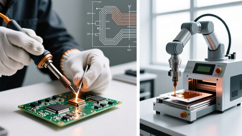
When engineers refer to an automatic soldering machine for THT or complex SMT rework, they are generally talking about two distinct categories: Desktop Robotic Soldering Arms and Selective Wave Soldering Systems.
Desktop Robotic Systems (e.g., Hakko FR-8000 Series)
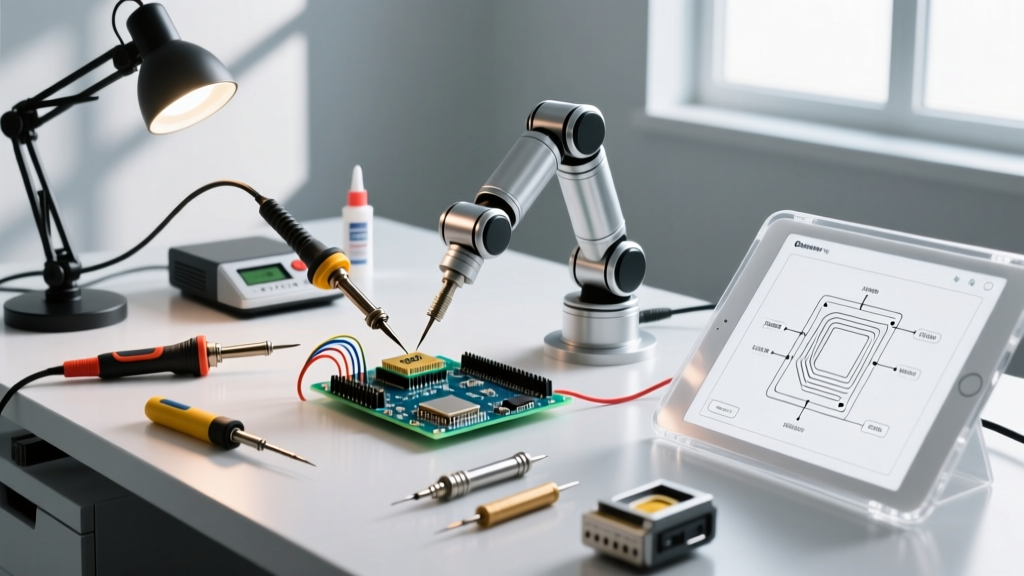
These machines utilize a multi-axis gantry to position a standard soldering iron tip and an automated wire feeder over the joint. They excel in environments where boards cannot be subjected to the thermal shock of a wave pot. Programming a robotic arm requires defining the X-Y-Z coordinates, dwell time, and solder feed length for every single pin. While a machine like the Hakko robotic soldering systems can achieve incredible repeatability, the initial programming time can take 2 to 4 hours for a complex 500-pin board. Therefore, they are highly inefficient for runs of fewer than 100 boards.
Inline Selective Wave Soldering (e.g., PILLARHOUSE Jade MKII)
Selective wave machines use a miniature, localized solder wave (often nitrogen-blanketed to reduce dross) that moves beneath the PCB, soldering only specific through-hole pads while avoiding nearby SMT components. In 2026, modern selective machines utilize precision drop-jet fluxers that apply flux with sub-millimeter accuracy, eliminating the need for expensive masking fixtures. However, the solder pot temperature for SAC305 (lead-free) alloy must be maintained at roughly 265°C to 280°C, which imposes strict thermal limits on nearby heat-sensitive plastic connectors.
Manual Soldering: The Unkillable Workhorse
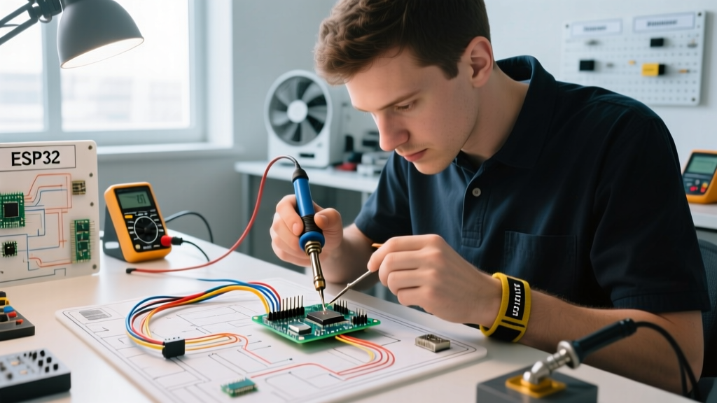
Despite the allure of automation, manual soldering using high-end stations like the JBC CD-2BQF or Weller WE1010 remains unbeatable for specific scenarios. The primary advantage of a human operator is real-time thermal feedback.
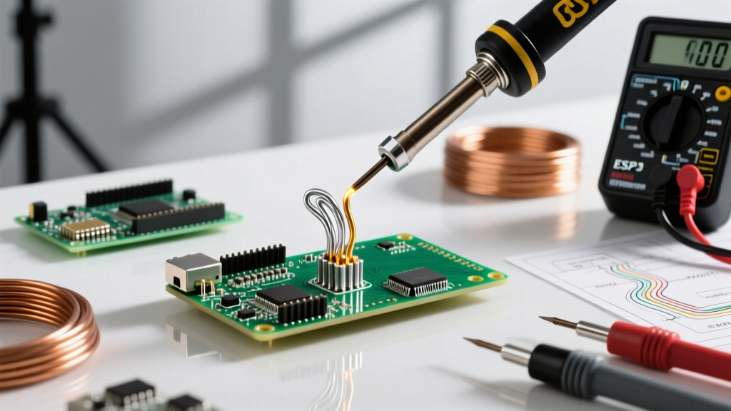
When soldering a ground-plane pin directly adjacent to a delicate 0.4mm pitch QFP, an automatic soldering machine might apply a standardized 3-second dwell time, potentially lifting the pad or melting the adjacent SMT component's plastic housing. A skilled technician, referencing the NASA Workmanship Training Program guidelines, will dynamically adjust their iron angle, use a broader chisel tip to increase surface contact, and pull away the exact millisecond the solder wicks into the barrel, ensuring IPC Class 3 hole-fill requirements without thermal damage.
Expert Insight: Mixed thermal mass is the enemy of automation. If your PCB features heavy copper pours (2oz+) on one side and ultra-fine signal traces on the other, the rigid thermal profile of an automatic soldering machine will either result in cold joints on the heavy pours or scorched pads on the fine traces. Manual soldering with active-tip technology (like JBC cartridges) is mandatory here.
Break-Even Analysis: When Does Automation Pay Off?
To justify the capital expenditure of an automatic soldering machine, you must calculate the break-even point based on labor savings and defect reduction. Let us look at a realistic 2026 scenario:
- Technician Burdened Labor Rate: $35.00 / hour
- Manual Soldering Time per Board: 12 minutes (0.2 hours) = $7.00 labor cost
- Robotic Machine Cycle Time per Board: 3 minutes (0.05 hours) = $1.75 labor cost (supervision)
- Savings per Board: $5.25
If you purchase a mid-range desktop robotic soldering arm for $18,000, you will need to process roughly 3,428 boards just to break even on the hardware cost, excluding maintenance, tip replacements, and programming time. If your annual volume is under 2,000 boards, manual soldering is mathematically superior.
Failure Modes and Defect Analysis
Understanding how each method fails is crucial for quality control managers adhering to IPC-A-610 standards.
Manual Soldering Defects
- Cold Joints: Caused by insufficient dwell time or removing the iron before the flux has fully activated and the solder has wetted the barrel.
- Pad Lifting: Operator error; leaving a 400°C iron on a pad for >4 seconds, degrading the FR-4 epoxy bond.
- Solder Bridges: Excessive manual solder wire feed, particularly on tight-pitch multi-pin connectors.
Automatic Soldering Machine Defects
- Flux Splatter: Drop-jet fluxers operating at too high a pressure can cause flux to bounce off the pad and contaminate nearby test points, causing false failures in ICT (In-Circuit Testing).
- Shadowing Effect: In selective wave soldering, tall components (like electrolytic capacitors) block the miniature wave from reaching adjacent pins, resulting in incomplete wetting.
- Wire Feed Jams: Robotic arms relying on mechanical wire feeders can experience micro-jams if the solder wire oxidizes or kinks, leading to starved joints that visual inspection cameras might miss.
Final Verdict: Which Method Wins?
There is no universal winner; the correct choice is dictated by your production volume and board topology.
Choose Manual Soldering if: You are running high-mix, low-volume (HMLV) production, dealing with extreme mixed thermal mass, or building prototypes where design iterations happen weekly. Invest in premium active-tip stations to minimize operator fatigue and ensure IPC compliance.
Choose an Automatic Soldering Machine if: You are scaling past 5,000 units annually, your THT components are located on the same side of the board with consistent thermal masses, and you need to eliminate human variability to secure medical or automotive contracts. For mid-volume, desktop robotic arms offer the best bridge between flexibility and automation, while inline selective wave systems are mandatory for high-volume, uninterrupted manufacturing.