
The Solderless Decision Matrix: When to Skip the Iron
While IPC-J-STD-001 remains the gold standard for electronic assemblies, thermal-sensitive components, field repairs, and rapid prototyping often demand alternatives. Knowing exactly how to attach wires to a circuit board without soldering requires understanding the mechanical and electrical limits of each method. As of 2026, advancements in silver-filled epoxies and micro-crimp technologies have made solderless connections viable for long-term deployment, not just temporary testing.
Use the decision framework below to select the optimal method based on your specific environmental and electrical constraints.
| Method | Best Use Case | Tensile/Shear Strength | Volume Resistivity | Est. Cost per Joint |
|---|---|---|---|---|
| Silver Conductive Epoxy | Thermal-sensitive ICs, flexible substrates | High (1,500+ psi shear) | < 0.001 Ω·cm | $0.15 - $0.40 |
| Wire Wrapping (30 AWG) | Aerospace prototyping, dense backplanes | Very High (Gas-tight) | N/A (Copper-to-Copper) | $0.02 - $0.05 |
| Micro-Crimp Housings (JST/Molex) | Modular wire-to-board interfaces | Moderate (Depends on housing latch) | N/A (Metal pin contact) | $0.08 - $0.25 |
| Z-Axis Conductive Tape | Temporary sensor patches, flex circuits | Low (Adhesive dependent) | Anisotropic (Z-axis only) | $0.05 - $0.10 |
Method 1: Silver-Filled Conductive Epoxy
Conductive epoxies are the premier choice when attaching wires to surface-mount pads or thermal-sensitive components that would be destroyed by a 350°C soldering iron. These adhesives use a resin matrix loaded with microscopic silver flakes that establish electrical continuity once cured.
Product Spotlight: MG Chemicals 8331
The MG Chemicals 8331 is a two-part silver epoxy widely used in industrial repairs. It offers a volume resistivity of less than 0.0006 Ω·cm, making it highly efficient for low-to-medium current traces (up to 2-3 Amps depending on trace width and epoxy volume).
- Mix Ratio: 1:1 by weight or volume.
- Cure Time: 24 hours at 24°C (room temperature), or 15 minutes at 65°C.
- Shelf Life: 24 months (unopened, refrigerated storage recommended for maximum 2026 shelf stability).
- Cost: Approximately $35 to $45 for a 28-gram dual-syringe kit.
Application Protocol & Failure Modes
The most common failure mode with conductive epoxy is oxidation at the pad interface prior to curing. To prevent this, scrub the PCB pad and the stripped wire tip with 99% isopropyl alcohol (IPA) and a fiberglass scratch pen. Apply a minimal dot of the mixed epoxy—excess resin acts as an insulator and increases joint resistance. Secure the wire with polyimide (Kapton) tape while curing to prevent micro-movements that can fracture the silver flake matrix before cross-linking is complete.
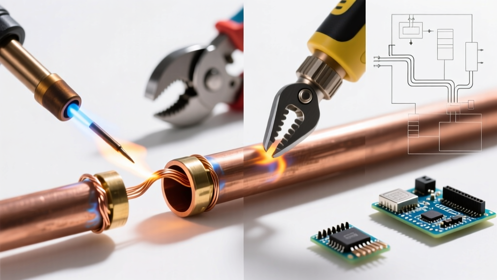
Method 2: Wire Wrapping for Gas-Tight Prototyping
Before the dominance of multi-layer PCBs, wire wrapping was the backbone of telecommunications and aerospace backplanes. Today, it remains a highly reliable method for attaching solid-core wires to square or rectangular through-hole pins without solder.
The Physics of a Gas-Tight Connection
Wire wrapping involves tightly coiling 30 AWG or 28 AWG solid-core Kynar-coated wire around a sharp-edged terminal. The high pressure (often exceeding 40 grams of pull force per wrap) cold-welds the copper wire to the terminal, cutting through surface oxides to create a gas-tight seal. This prevents oxygen from reaching the bare metal, effectively eliminating long-term corrosion.
Required Tooling
Do not attempt this with standard pliers. You need a dedicated wire wrap tool with a precision-machined bit and a mechanical clutch to prevent wire breakage.
- Manual Tool: Jonard WSU-30M (approx. $22). Excellent for low-volume lab work.
- Wire: 30 AWG solid-core copper with Kynar insulation (approx. $15 for a 100ft spool). Kynar is preferred over PVC because it does not melt or strip back under friction during the wrapping process.
Expert Insight: Wire wrapping is strictly limited to solid-core wire and square/rectangular posts. It cannot be used on stranded wire or round surface-mount pads. If your PCB only features round vias, this method is not viable.
Method 3: Micro-Crimp Housings and ZIF Connectors
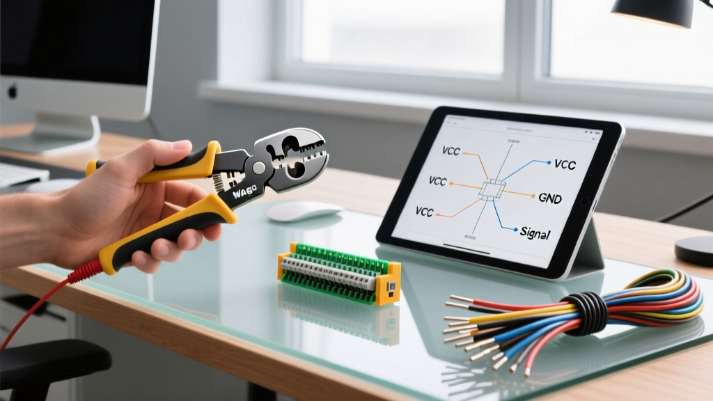
If your goal is to attach wires to a circuit board in a way that allows for future disassembly, modular crimp housings are the industry standard. Rather than bonding the wire directly to the board, you solder a low-profile header to the PCB once, and use solderless crimped pins for the wire side.
JST SH and Molex PicoClasp Ecosystems
For modern, high-density boards, the 1.0mm pitch JST SH series and the 1.25mm pitch Molex PicoClasp are the dominant form factors.
- Wire Preparation: Strip exactly 1.5mm of insulation from a 28-30 AWG stranded silicone wire.
- Crimping: Use a precision micro-crimp tool like the Engineer PA-09 (approx. $28). This tool features interchangeable dies that perfectly fold the metal crimp barrel around the wire strands without severing them.
- Mating Cycles: High-quality JST connectors are rated for 30 to 50 mating cycles before the internal phosphor bronze leaf springs lose their tension.
Zero Insertion Force (ZIF) Alternatives
For flat ribbon cables or flexible printed circuits (FPC), ZIF connectors utilize a mechanical cam to clamp down on exposed copper traces. While technically a board-mounted component, the wire-to-board interface is entirely solderless on the cable side, relying on friction and normal force. Ensure the FPC cable has a stiffener layer applied to the insertion end to prevent the cam from crushing the delicate polyimide substrate.
Method 4: Z-Axis Conductive Adhesive Tapes
Z-axis (anisotropic) conductive tapes, such as the 3M 7303 series, are engineered to conduct electricity only through the thickness of the tape (the Z-axis), while remaining insulative on the X and Y planes.
This allows you to bridge a wire to a densely packed PCB pad without risking short circuits to adjacent traces. The tape contains nickel or silver-coated polymer spheres suspended in an adhesive matrix. When compressed between the wire and the pad, the spheres crush and establish a vertical electrical path.
- Application: Apply moderate, even pressure (approx. 20-30 psi) using a heated press or a specialized manual roller.
- Limitation: Z-axis tapes are highly sensitive to peel forces. They must be mechanically secured with an overlying layer of non-conductive Kapton tape or UV-curable conformal coating to survive in high-vibration environments.
Critical Edge Cases and Environmental Failures
When bypassing traditional solder joints, you must engineer around the environmental stresses that solder naturally mitigates.
1. Coefficient of Thermal Expansion (CTE) Mismatch
FR4 fiberglass PCBs and copper wires expand at different rates when heated. Solder is somewhat ductile and absorbs this stress. Conductive epoxy, however, cures into a rigid thermoset plastic. If your device operates in environments with extreme temperature cycling (e.g., automotive or outdoor IoT enclosures), the CTE mismatch can cause the epoxy joint to micro-fracture. Solution: Add a strain relief loop to the wire and encapsulate the joint in a flexible silicone potting compound like Dow Sylgard 184.
2. Vibration and Mechanical Shock
Solderless connections—particularly Z-axis tapes and conductive epoxies—have poor peel strength. While they may withstand 1,500 PSI of shear force (sliding parallel to the board), a 5-pound upward pull on the wire can instantly rip the copper pad off the PCB. Solution: Always use a secondary mechanical anchor. Secure the wire to the board using UV-curable acrylic adhesives (e.g., Loctite 3108) a few millimeters away from the electrical joint to absorb all mechanical tension.
Summary: Choosing Your Solderless Path
Deciding how to attach wires to a circuit board without soldering is not about finding a universal replacement for the soldering iron, but rather selecting the right tool for specific constraints. Use silver epoxy for permanent, thermally-sensitive surface-mount repairs. Rely on wire wrapping for ultra-reliable, gas-tight through-hole prototyping. Deploy micro-crimp housings when modularity and field-replaceability are required. By matching the mechanical and electrical properties of these methods to your exact operating environment, you can achieve production-grade reliability without ever melting a drop of rosin flux.
For further reading on industry assembly standards and when soldering remains strictly mandatory, refer to the IPC J-STD-001 Requirements for Soldered Electrical and Electronic Assemblies. Additionally, detailed technical data on conductive adhesive formulations can be found via the Chemtronics CircuitWorks technical documentation.