
The Shift to Induction in Modern Manufacturing
In high-volume electronics manufacturing and heavy industrial fabrication, maintaining thermal equilibrium across massive ground planes and thick copper busbars is a persistent challenge. As we navigate the production demands of 2026, the shift toward high-density power electronics, 800V EV (Electric Vehicle) architectures, and advanced RF modules has pushed traditional resistive soldering irons to their absolute thermal limits. This is where soldering with induction has transitioned from a specialized laboratory technique to a cornerstone of both automated and manual industrial assembly lines.
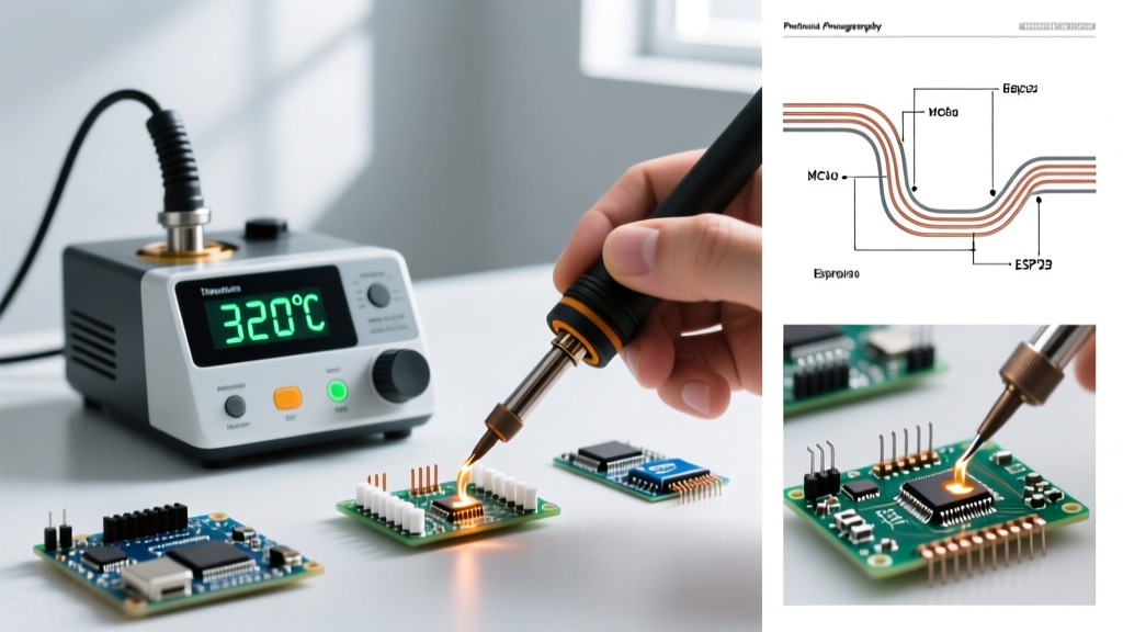
Unlike conventional stations that rely on a resistive ceramic heater and a thermocouple feedback loop—which inherently suffers from thermal lag—induction systems utilize high-frequency electromagnetic fields to generate heat directly within the soldering tip or the workpiece itself. This guide explores the physics, hardware ecosystems, and specific industrial applications of induction soldering, providing manufacturing engineers and procurement teams with the actionable data needed to optimize their production floors.
The Physics of Curie-Point Temperature Control
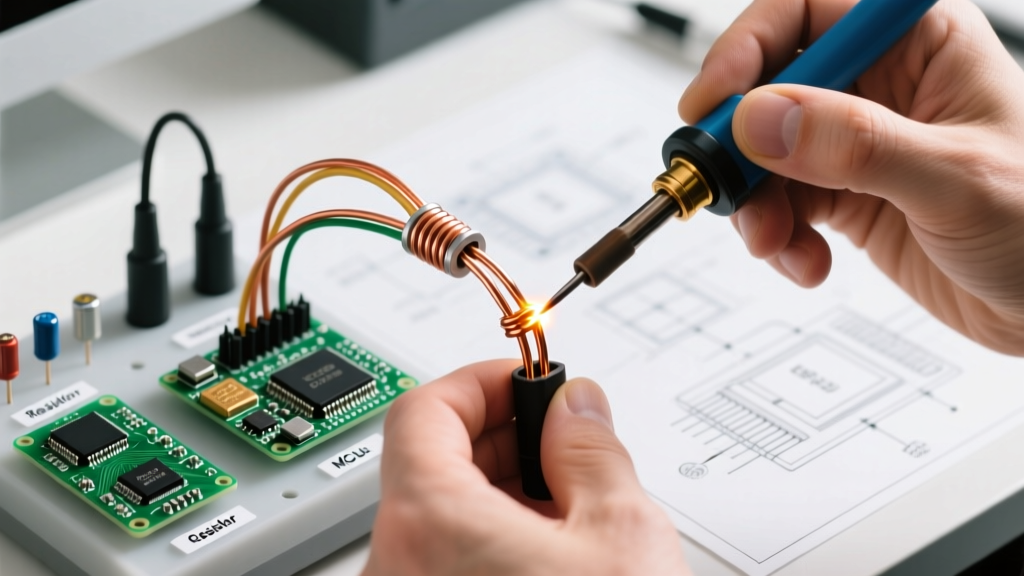
To understand why induction dominates in demanding sectors like aerospace and automotive wiring, you must look past basic Joule heating. Induction soldering relies on the skin effect and eddy currents. An RF (Radio Frequency) generator sends an alternating current through a coil in the handpiece or robotic end-effector, creating a rapidly alternating magnetic field. This field induces eddy currents in the ferromagnetic core of the soldering tip, causing it to heat up instantly due to electrical resistance.
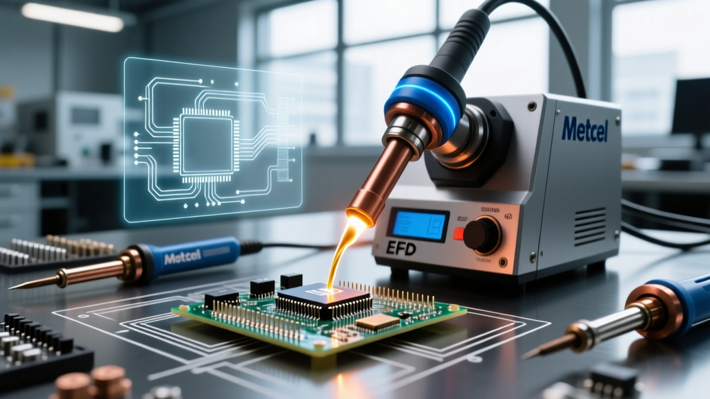
The true genius of systems like Metcal's SmartHeat technology lies in the Curie point. The tip is coated with a specific ferromagnetic alloy engineered to lose its magnetic properties at a precise temperature (e.g., 350°C, 400°C, or 450°C). Once the tip reaches its Curie temperature, the eddy currents cease, and heating stops instantly. As soon as the tip touches a cold solder joint and drops below the Curie point, magnetism returns, and full RF power is applied again. This results in zero thermal overshoot and eliminates the need for delicate, failure-prone thermocouple sensors inside the tip.
2026 Industrial Hardware Matrix
Not all induction systems are built for the same task. Benchtop PCB assembly requires vastly different RF characteristics than automated brazing of copper roofing or EV battery tabs. Below is a comparison of the dominant induction platforms currently deployed in industrial environments.
| System / Brand | Target Application | RF Frequency | Approx. CapEx (2026) |
|---|---|---|---|
| Metcal MX-5200 | Manual PCB, RF Cans, High-Density SMT | 470 kHz | $1,100 - $1,350 |
| Quick 303A | Budget Industrial, General Wire Tinning | 400 kHz | $250 - $350 |
| EFD Induction Minac | Automated EV Busbars, Heavy Copper Brazing | 10 - 25 kHz (Variable) | $12,000 - $25,000+ |
| Okaya SE-900H | Robotic Soldering Cells, Continuous Duty | 13.56 MHz | $2,800 - $3,500 |
Core Industry Applications
1. EV Battery Tab and Busbar Welding/Soldering
In the electric vehicle sector, connecting thick copper and aluminum busbars requires immense thermal energy. Traditional irons stall when faced with the thermal mass of a 4/0 AWG cable or a 5mm copper busbar. High-power induction systems (like those from EFD Induction) use custom-profiled inductor coils to heat the joint area volumetrically. By applying a pre-form solder ring and flux, the induction field heats the base metals to 300°C in under 3 seconds, creating a metallurgical bond without degrading the surrounding battery cell insulation.
2. Aerospace RF Shielding and Ground Planes
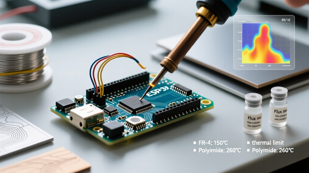
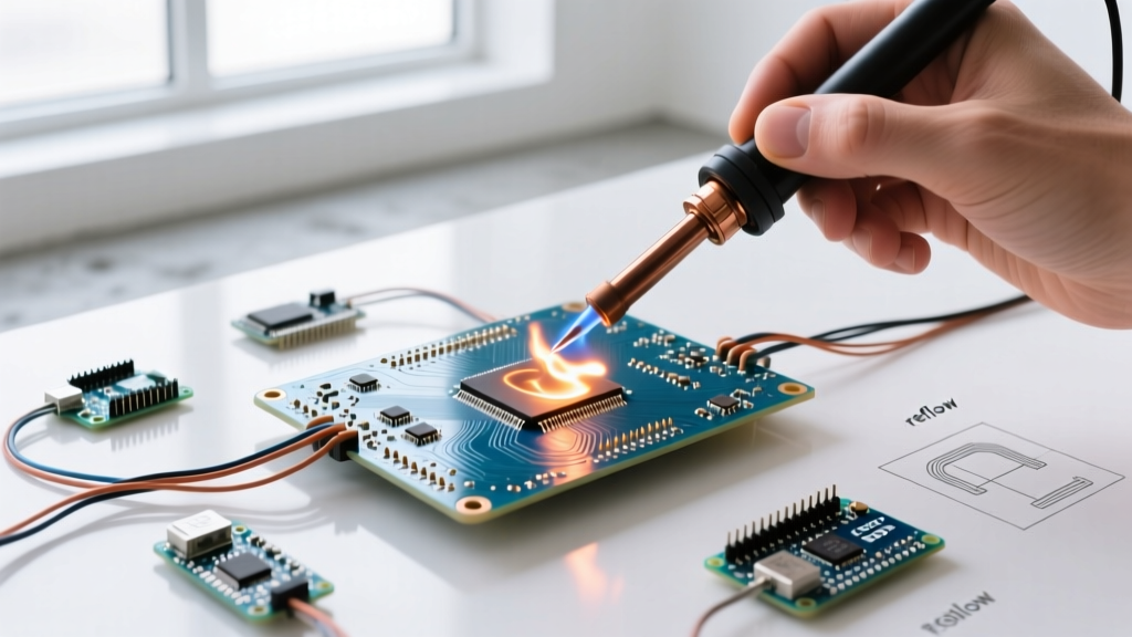
Aerospace PCBs frequently feature extensive copper pours and RF shielding cans that act as massive heat sinks. When operators use resistive irons, they often dwell on the joint for 10+ seconds, risking delamination of the FR-4 or polyimide substrate. Soldering with induction at 470 kHz ensures that the moment the tip contacts the ground plane, the localized Curie-point regulation dumps maximum wattage (often peaking over 120W instantaneously) directly into the joint, achieving reflow in 1.5 to 2.5 seconds.
3. Automated Robotic Soldering Cells
For high-volume consumer electronics, robotic soldering arms equipped with 13.56 MHz induction heads are becoming the standard. The higher frequency allows for a smaller, lighter coil assembly on the robot wrist, reducing payload and increasing movement speed. Furthermore, because induction tips lack internal wiring or thermocouples, they are highly resistant to the mechanical vibration and Z-axis impact forces inherent in automated CNC soldering routing.
Critical Failure Modes and Edge Cases
While induction systems are remarkably robust, they introduce unique failure modes that maintenance teams must monitor. Understanding these edge cases is vital for maintaining OEE (Overall Equipment Effectiveness) on the production line.
- RF Coil Carbonization: If rosin-based or synthetic flux splatters onto the internal RF coil inside the handpiece, it can bake into a conductive carbon layer. This creates parasitic capacitance, leading to Standing Wave Ratio (SWR) spikes. The generator will detect the impedance mismatch and shut down to protect its MOSFETs. Fix: Implement weekly isopropyl alcohol flushes of the handpiece cavity.
- Tip Plating Dissolution: Induction tips recover heat so aggressively that operators sometimes use them to 'scrub' oxidized pads. The combination of high thermal recovery and mechanical friction strips the iron plating off the copper core, leading to rapid tip dissolution. Fix: Mandate the use of automated tip tinning stations at the end of every shift.
- Ferromagnetic Contamination: In mixed-metal fabrication environments, steel dust or nickel shavings can become magnetically attracted to the handpiece coil area, altering the inductance and causing erratic temperature behavior. Fix: Maintain strict positive-pressure cleanroom protocols around induction benchtop stations.
ROI, Traceability, and IPC Compliance
From a procurement perspective, the initial capital expenditure for a benchtop induction station like the Metcal MX-5200 is roughly 400% higher than a standard ceramic resistive station. However, the Total Cost of Ownership (TCO) tells a different story. Because induction tips do not contain fragile glass thermocouples or internal heater wires, their physical lifespan is often 3x to 5x longer than cartridge tips, provided the iron plating is maintained.
More importantly, compliance with modern manufacturing standards requires strict thermal profiling. According to the guidelines set forth in IPC J-STD-001, manufacturers must prove that thermal excursion limits were not violated during the soldering process. Advanced 2026 induction generators feature built-in RF power logging. Because the power draw correlates directly to the thermal demand of the joint, the system can output a digital log proving that the joint reached the necessary liquidus temperature without dwelling excessively. This data can be piped directly into the factory's MES (Manufacturing Execution System) for per-board traceability.
Engineering Insight: When validating a new induction soldering process for a high-thermal-mass board, do not rely solely on the manufacturer's stated Curie temperature. Always run a thermal couple profile on a dummy board with a K-type thermocouple embedded in the via barrel. The actual joint temperature will lag behind the tip's Curie point by 15°C to 30°C depending on the solder paste alloy (e.g., SAC305 vs. Sn63Pb37) and the flux volatility. For deeper physics on how alternating magnetic fields interact with varying metal geometries, review the fundamentals of induction heating to properly design custom coil profiles for your specific workpieces.
Final Verdict for 2026 Production Floors
Soldering with induction is no longer just a premium alternative; it is a thermal management necessity for modern, high-reliability manufacturing. Whether you are tinning heavy-gauge automotive harnesses, assembling 5G mmWave transceivers, or programming robotic cells for continuous PCB assembly, the instantaneous thermal recovery and sensorless reliability of induction technology provide a distinct yield advantage. By matching the correct RF frequency and Curie-point alloy to your specific thermal mass requirements, you can eliminate cold solder joints, reduce substrate damage, and achieve full IPC traceability.