
The Metallurgy of the Joint: 2026 Expert Perspectives
In the rapidly evolving landscape of electronics assembly, mastering a specific soldering technique is no longer just about melting metal; it is an exercise in applied metallurgy and thermal management. As component densities increase and lead-free mandates become universally enforced across global supply chains, the margin for error has shrunk to near zero. To bridge the gap between amateur guesswork and professional reliability, we consulted three veteran electronics engineers and rework specialists to compile this definitive 2026 expert roundup.
Whether you are dealing with ultra-fine-pitch QFN packages or high-current through-hole connectors, the insights below will refine your approach, reduce thermal stress on your PCBs, and ensure your joints meet stringent IPC Standards for Class 2 and Class 3 assemblies.
Micro-Soldering and SMD Rework: Precision Over Power
Insight from Sarah Jenkins, Senior SMT Rework Technician at a Tier-1 Aerospace Contractor
When working with 0201 and 01005 surface-mount packages, brute force heat is the enemy. Sarah emphasizes that the modern soldering technique for micro-components relies on rapid thermal recovery rather than sheer wattage.
'Many hobbyists and even junior techs make the mistake of using massive chisel tips to 'force' heat into a tiny pad. This causes massive thermal shock and pad delamination. For 0201 components, I exclusively use a JBC C245 handle with a 118 series nano-tip. The cartridge-integrated heater design drops the tip temperature by only a few degrees upon contact, recovering in under 40 milliseconds.'
— Sarah Jenkins, SMT Rework Specialist
The Drag Soldering Technique for Fine-Pitch ICs
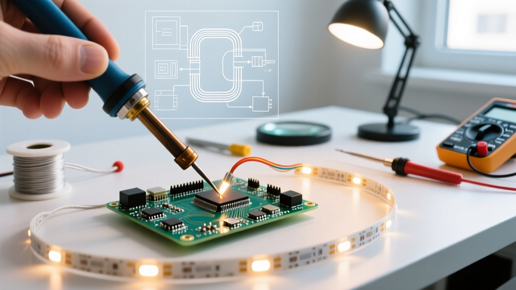
For 0.5mm pitch TQFP and QFN packages, Sarah recommends the drag soldering technique using a heavily fluxed board and a hollow-ground gull-wing tip.
- Preparation: Apply a generous layer of ROL0 (Rosin, Low Activation) tacky flux. Do not skimp; flux is your thermal bridge.
- Alloy Selection: Use Sn63/Pb37 (leaded) 0.031-inch diameter wire for prototyping and rework where permitted, as its eutectic 183°C melting point prevents component shifting during the cooling phase.
- Execution: Set the station to 310°C. Tilt the iron at a 45-degree angle, allowing a small bead of solder to form on the very edge of the tip. Drag across the pins at a steady pace of roughly 1 inch per second. The surface tension of the flux will automatically pull the solder into the individual pads, preventing bridges.
High Thermal Mass Through-Hole: Managing the Heat Sink
Insight from Marcus Vance, Power Electronics Engineer
Soldering heavy-gauge wires to large ground planes or multi-layer power boards requires a completely different soldering technique. The copper acts as a massive heat sink, pulling thermal energy away from the joint faster than a standard iron can supply it.
'If you are holding an iron to a 10oz copper ground plane for more than five seconds, you are doing it wrong and risking epoxy breakdown. The secret isn't turning your iron up to 450°C; it is preheating the board and using the correct tip geometry.'
— Marcus Vance, Power Electronics Engineer
Pro-Tip: The Preheat and Chisel Method
Marcus outlines a strict protocol for high-thermal-mass joints to comply with the workmanship requirements outlined by the NASA Electronic Parts and Packaging (NEPP) Program:
- Bottom Preheating: Use an IR preheater to bring the entire PCB ambient temperature up to 120°C - 130°C. This reduces the thermal delta the soldering iron must overcome.
- Tooling: Use a high-capacity station like the Weller WE1010 paired with a heavy XDS or ETA chisel tip. The thermal mass of the tip itself stores the energy required for the joint.
- Flux and Feed: Apply liquid no-clean flux directly into the barrel. Touch the flat face of the chisel tip simultaneously to the component lead and the barrel wall. Feed SAC305 (lead-free) wire directly into the intersection of the lead and pad, not onto the iron tip.
- Dwell Time: A properly executed high-mass joint should flow and fill the barrel in 2.5 to 3.5 seconds. Remove heat immediately once the solder wicks to the top of the barrel.
2026 Technique Selection Matrix
Selecting the right soldering technique requires matching your tooling, alloy, and thermal profile to the specific component architecture. Use the matrix below as a quick-reference guide for your workbench.
| Soldering Technique | Target Component | Optimal Tip Geometry | Base Temp (SAC305 Lead-Free) | Max Dwell Time |
|---|---|---|---|---|
| Drag Soldering | Fine-Pitch QFP / SOIC | Hollow Gull-Wing | 340°C - 360°C | Continuous (1 in/sec) |
| Nano-Soldering | 0201 / 01005 Passives | Micro-Conical (0.1mm) | 320°C - 340°C | 0.5 - 1.0 seconds |
| Sequential Pin | Standard DIP / Headers | Conical / Bevel | 350°C | 2.0 - 3.0 seconds |
| Preheated Barrel Fill | High-Current Terminals | Heavy Chisel (6mm+) | 360°C - 380°C | 3.0 - 4.5 seconds |
Advanced Troubleshooting: Beyond the Cold Joint
Even with perfect temperature control, environmental and material variables can introduce defects. Here is how our experts diagnose complex failure modes.
1. Tombstoning on Small Passives
The Failure: A 0402 capacitor stands on one end during reflow or hand soldering.
The Root Cause: Asymmetric thermal mass. One pad is connected to a wide trace (acting as a heat sink), while the other is connected to a thin trace. The pad with less thermal mass reaches the solder's liquidus temperature first, creating surface tension that pulls the component upright.
The Fix: When using a hand soldering technique, apply the iron tip so it bridges both pads simultaneously, or pre-tin the heavier pad first to equalize the thermal load before placing the component.
2. Solder Wicking and Starved Joints
The Failure: Solder climbs entirely up the component lead, leaving the pad dry and the barrel unfilled.
The Root Cause: The iron tip was placed on the component lead rather than the pad. Heat travels up the lead, melting the solder there, and capillary action pulls the molten alloy away from the cooler pad.
The Fix: Always touch the iron to the PCB pad first, or exactly at the intersection of the pad and lead. Never feed solder directly onto the iron tip and 'wipe' it onto the joint; this burns off the flux core before the metal can wet the copper.
3. Pad Lifting and Measling
The Failure: The copper pad separates from the FR-4 substrate, or white spots (measling) appear inside the fiberglass.
The Root Cause: Exceeding the glass transition temperature (Tg) of the PCB laminate for an extended period. Standard FR-4 has a Tg of roughly 130°C to 140°C. Prolonged exposure to 380°C+ iron temperatures causes the epoxy resin to expand and detach from the copper foil.
The Fix: Rely on thermal preheating to reduce the required iron temperature, and strictly enforce a 3-second maximum dwell time rule. If a joint requires more than 4 seconds of direct iron contact, your tip geometry is too small for the thermal mass.
Frequently Asked Questions
Is it necessary to clean 'no-clean' flux after soldering?
While ROL0 and ROL1 'no-clean' fluxes are designed to leave a benign, hard residue that does not cause dendritic growth under normal conditions, cleaning is highly recommended if you are applying a conformal coating later. The coating will not adhere properly to flux residue, leading to delamination in harsh environments.
How often should I re-tin my soldering iron tip in 2026?
With modern lead-free alloys like SAC305 being highly corrosive to iron plating, you should re-tin your tip immediately after every joint and before placing the iron back in its holder. A thick blob of leaded solder (Sn63/Pb37) left on the tip during storage acts as a sacrificial layer, preventing the lead-free alloy from pitting and dissolving the iron plating.
What is the best soldering technique for enamel-coated magnet wire?
Do not scrape the enamel with a blade, as this nicks the copper and creates a weak point. Instead, use a 'pot soldering' technique. Set your iron to 380°C, apply a large bead of flux-cored solder to the tip, and bury the tip of the magnet wire in the molten bead for 3-4 seconds. The heat and flux will chemically strip the polyurethane enamel and tin the wire in one step.