
The Anatomy of the Ultimate Simple Arduino Project
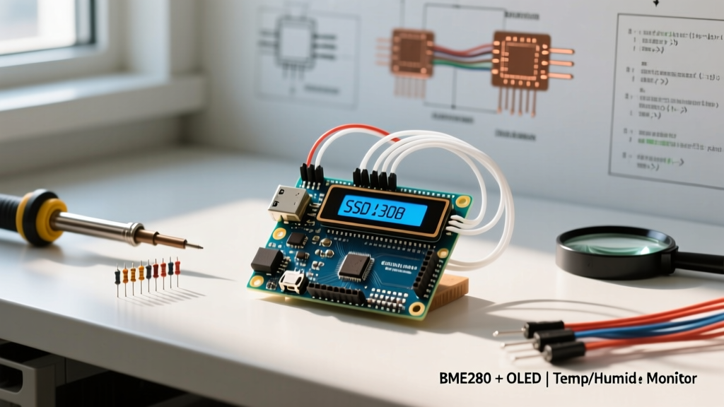
When makers, hobbyists, and engineering students search for a simple arduino project, they frequently land on outdated tutorials featuring the DHT11 sensor or basic LED blinking. While these serve as adequate introductions to digital I/O, they fail to represent modern embedded systems design. In 2026, the standard for entry-level sensor projects demands higher precision, bus-based communication, and non-blocking code architecture. The ultimate simple arduino project that bridges the gap between beginner-friendly wiring and professional-grade environmental monitoring is the BME280 Microclimate Monitor paired with an SSD1306 I2C OLED display.
This build moves beyond simple analog readings and introduces the Inter-Integrated Circuit (I2C) protocol, sensor calibration, and real-time data visualization. By the end of this guide, you will have a functional, low-power environmental station capable of tracking temperature, relative humidity, and barometric pressure with laboratory-grade accuracy, all for under $15 in component costs.
Component Selection: Why the BME280 Wins
The heart of this simple arduino project is the Bosch BME280 environmental sensor. Unlike older capacitive humidity sensors, the BME280 integrates a piezoresistive pressure sensor, a capacitive humidity sensor, and a resistive temperature sensor into a single 2.5 x 2.5 mm LGA package. It communicates via I2C or SPI and features an internal ASIC that handles complex signal conditioning and temperature compensation.
| Sensor Model | Interface | Humidity Accuracy | Response Time | Avg. Cost (2026) |
|---|---|---|---|---|
| DHT11 | Custom 1-Wire | ±5% RH | Slow (1Hz max) | $1.50 |
| DHT22 (AM2302) | Custom 1-Wire | ±2% RH | Slow (0.5Hz max) | $4.00 |
| AHT20 | I2C | ±2% RH | Fast | $2.50 |
| BME280 (Bosch) | I2C / SPI | ±3% RH (±2% typical) | Ultra-Fast (up to 157Hz) | $3.00 - $14.95 |
For the display, the 0.96-inch SSD1306 128x64 I2C OLED is the undisputed champion of microcontroller projects. It requires no backlight, draws roughly 20mA when fully illuminated, and offers crisp contrast for rendering data dashboards.
Bill of Materials (BOM)
- Microcontroller: Arduino Nano (Clone or Official) - $4.50 to $22.00
- Sensor: BME280 Breakout Board (Generic or Adafruit 2652) - $3.00 to $14.95
- Display: SSD1306 128x64 I2C OLED - $3.50
- Miscellaneous: Breadboard, jumper wires, 4.7kΩ pull-up resistors (if needed) - $2.00
Critical Hardware Wiring: Avoiding the I2C Voltage Trap
The most common point of failure in any I2C-based simple arduino project is improper voltage level matching and bus capacitance. The BME280 is strictly a 3.3V device. Feeding 5V directly into the VCC pin of a bare Bosch chip will instantly destroy the internal ASIC.
However, the market is flooded with generic BME280 breakout boards. High-quality boards (like those from Adafruit or SparkFun) include an onboard 3.3V LDO regulator and logic-level shifting MOSFETs, allowing you to safely power them from the Arduino's 5V pin. Generic $3 modules from overseas marketplaces often lack these regulators, exposing the 3.3V logic directly to the VCC pin.
The Wiring Matrix
- VCC: Connect to Arduino 3.3V (for generic modules) or 5V (for Adafruit/SparkFun modules with onboard LDOs).
- GND: Connect to Arduino GND.
- SCL: Connect to Arduino A5 (Nano/Uno hardware I2C clock).
- SDA: Connect to Arduino A4 (Nano/Uno hardware I2C data).
Engineering Pro-Tip: The I2C specification requires pull-up resistors on the SDA and SCL lines. While the Arduino's internal pull-ups (roughly 30kΩ) can sometimes work for short, single-device buses, they are far too weak for reliable communication. If your OLED and BME280 share the same bus, add external 4.7kΩ pull-up resistors tied to 3.3V. This ensures sharp signal edges and prevents data corruption, especially if your jumper wires exceed 15cm in length. For a deeper understanding of bus capacitance and timing, refer to the official Arduino Wire library documentation.
Software Configuration and I2C Address Conflicts
Before writing the main logic, you must resolve I2C addressing. The BME280 supports two distinct I2C addresses: 0x76 and 0x77. The address is determined by the state of the SDO (Serial Data Out) pin on the sensor die. On most generic breakout boards, SDO is hardwired to GND, resulting in the 0x76 address. The SSD1306 OLED typically resides at 0x3C.
To manage these components, install the following libraries via the Arduino Library Manager:
- Adafruit BME280 Library (and its dependency, Adafruit Unified Sensor)
- Adafruit SSD1306 (and Adafruit GFX Library)
Non-Blocking Code Architecture
A hallmark of a well-engineered simple arduino project is the avoidance of the delay() function. Using delay() halts the microcontroller's CPU, preventing background tasks, button debouncing, or future Wi-Fi telemetry from executing. Instead, we use a non-blocking millis() timer to poll the sensor every 2,000 milliseconds.
Below is the structural logic for the main loop:
unsigned long previousMillis = 0;
const long interval = 2000; // Poll every 2 seconds

void loop() {
  unsigned long currentMillis = millis();

  if (currentMillis - previousMillis >= interval) {
    previousMillis = currentMillis;

    // Read Sensor Data
    float temp = bme.readTemperature();
    float hum = bme.readHumidity();
    float pres = bme.readPressure() / 100.0F; // Convert Pa to hPa

    // Update OLED Display
    updateDisplay(temp, hum, pres);
  }

  // Other non-blocking tasks can run here freely
}
This architecture ensures that the I2C bus is only queried at precise intervals, reducing bus congestion and allowing the BME280's internal digital filters to settle between readings. According to the Bosch Sensortec BME280 datasheet, the sensor requires a brief settling time after initialization to achieve optimal humidity accuracy; a 2-second polling interval naturally accommodates this requirement without complex state machines.
Real-World Failure Modes and Calibration
Even the most straightforward sensor projects encounter real-world physics issues. When building this microclimate monitor, be prepared to troubleshoot the following edge cases:
1. The Soldering Flux Humidity Trap
The BME280 measures humidity using a polyimide capacitive sensing element covered by a microscopic PTFE membrane. If you solder the header pins yourself, rosin-based soldering flux can easily wick into this membrane. Flux residue blocks water vapor, causing the sensor to permanently read a stuck humidity value (often around 40% or spiked to 95%). Solution: Always clean the area around the sensor with 99% isopropyl alcohol and a soft-bristle brush immediately after soldering, or purchase pre-assembled modules with headers already attached via reflow ovens.
2. Thermal Self-Heating Errors
If you mount the BME280 directly above the Arduino Nano's voltage regulator or the back of the OLED display, the thermal radiation will skew your temperature readings upward by 2°C to 4°C. Solution: Use longer jumper wires to physically separate the sensor from heat-generating components, or mount the BME280 in a ventilated, 3D-printed Stevenson screen enclosure.
3. OLED Flickering and I2C Bus Drops
If your OLED display randomly flickers or the serial monitor outputs NaN (Not a Number) for sensor readings, your I2C bus is likely experiencing voltage sag. The SSD1306's internal charge pump can draw sudden current spikes when rendering full white screens. Solution: Place a 100µF electrolytic capacitor across the 5V and GND rails on your breadboard to stabilize the power delivery and smooth out transient voltage drops.
Conclusion
Building a simple arduino project does not mean compromising on engineering best practices. By selecting the Bosch BME280, respecting I2C electrical characteristics, and implementing non-blocking code, you elevate a basic beginner tutorial into a robust, deployable microclimate monitor. This foundational architecture serves as the perfect springboard for advanced iterations, such as adding an ESP8266 Wi-Fi module for MQTT cloud logging or integrating a lithium-ion battery management system for off-grid weather station deployments.