
The Shift to Sensor Fusion in Arduino Robotics Projects
The era of simple ultrasonic sensors and line-following IR arrays is over. As of 2026, competitive and functional Arduino robotics projects demand robust sensor fusion to navigate dynamic, real-world environments reliably. Relying on a single modality—like basic infrared distance sensing—leads to catastrophic edge-case failures when encountering glass walls, matte black surfaces, or high-ambient sunlight. To build a truly autonomous maze navigator or warehouse rover, engineers must merge micro-LiDAR, Time-of-Flight (ToF) SPAD arrays, and 9-DOF inertial measurement units (IMUs).
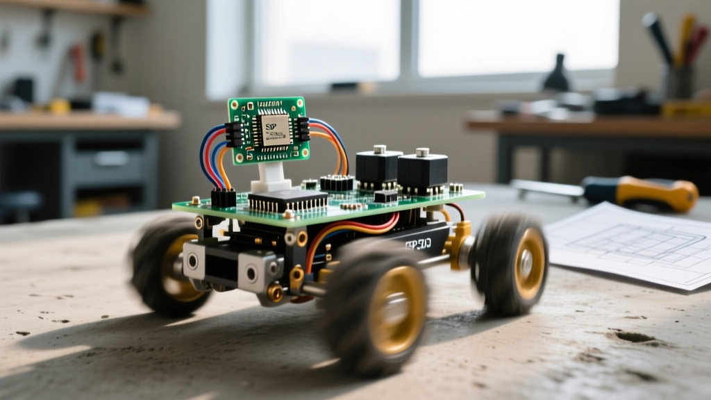
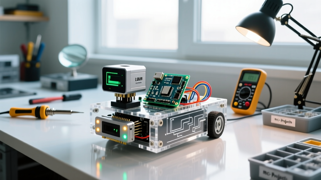
This guide details the architecture, power distribution, and algorithmic logic required to build a sensor-driven autonomous rover using the Arduino Nano ESP32. By fusing long-range UART LiDAR with short-range I2C ToF sensors and dead-reckoning odometry, we eliminate the blind spots that plague amateur robotics builds.
Hardware Bill of Materials (BOM) & Selection Logic
Selecting the right microcontroller and sensors is critical. While the classic ATmega2560 has abundant I/O, its 5V logic and limited SRAM make it unsuitable for modern 3.3V sensor fusion and mapping arrays. The Arduino Nano ESP32 provides native 3.3V logic, a dual-core 240MHz processor, and 512KB of SRAM, making it the optimal brain for this build.
| Component | Model / Specification | Est. Cost | Role in Architecture |
|---|---|---|---|
| Microcontroller | Arduino Nano ESP32 | $18.50 | Core processing, I2C/UART routing, sensor fusion math. |
| Long-Range LiDAR | Benewake TFMini Plus (UART) | $39.99 | 12m range, 850nm IR, 1000Hz polling for fast obstacle detection. |
| Short-Range ToF | Pololu VL53L1X Carrier | $12.95 | 4m range, 940nm SPAD array, detects glass and transparent obstacles. |
| IMU | Adafruit BNO055 | $34.95 | 9-DOF absolute orientation, internal sensor fusion for Euler/Quaternions. |
| Motor Driver | Pololu Dual TB6612FNG | $5.95 | 1.2A continuous per channel, PWM speed control, logic-level compatible. |
| Power Source | 2S LiPo (7.4V, 1500mAh) | $16.00 | High C-rating for motor stall currents and sensor spikes. |
Power Distribution: Avoiding the Linear Regulator Trap
A frequent point of failure in intermediate Arduino robotics projects is power regulation. A fully charged 2S LiPo battery outputs 8.4V. The Arduino Nano ESP32, BNO055, and VL53L1X all require a clean 3.3V rail, while the TFMini Plus and TB6612FNG motor driver logic require 5V.
The Thermal Math of Voltage Regulation
Novice builders often reach for an LM7805 linear regulator to step 8.4V down to 5V. This is a critical error. If your system draws a conservative 800mA (sensors + MCU + idle motors), the voltage drop across the LDO is 3.4V. The power dissipated as heat is calculated as:
P = V_drop × I = 3.4V × 0.8A = 2.72 Watts
A standard TO-220 package without an active heatsink will trigger thermal shutdown at roughly 1.5W to 2W, causing your robot to randomly reboot when the motors engage. Instead, you must use a switching buck converter. The Pololu Step-Down Voltage Regulator D24V10F5 operates at >90% efficiency, reducing heat dissipation to under 0.3W and ensuring stable voltage during motor stall events.
Sensor Modalities and Edge-Case Handling
True autonomy requires understanding the physics of your sensors. Fusing the TFMini Plus and the VL53L1X covers the blind spots inherent to each technology.
LiDAR vs. ToF: The Glass and Sunlight Problem
The TFMini Plus emits an 850nm infrared laser. While excellent for long-range (12m) mapping, 850nm IR is heavily present in natural sunlight. If your robot operates near a sunlit window or outdoors, the TFMini will experience signal saturation, returning erratic max-range values. Furthermore, standard IR LiDAR struggles with specular reflections off glass or acrylic.
The VL53L1X solves this. It uses a 940nm Vertical-Cavity Surface-Emitting Laser (VCSEL) paired with a Single Photon Avalanche Diode (SPAD) array. The 940nm wavelength, combined with narrow optical bandpass filters on the receiver, makes it highly immune to solar IR noise. While its practical range is limited to 4 meters, it reliably detects glass walls that the TFMini Plus will completely ignore.
Wiring Matrix and I2C Bus Management
The Arduino Nano ESP32 allows flexible pin mapping for I2C and UART, which is vital for keeping wiring harnesses short and reducing electromagnetic interference (EMI) from the motors.
| Sensor / Module | Protocol | ESP32 GPIO Pins | Default I2C Address |
|---|---|---|---|
| TFMini Plus | UART (115200 baud) | TX: GPIO 43, RX: GPIO 44 | N/A |
| VL53L1X | I2C | SDA: GPIO 16, SCL: GPIO 17 | 0x29 |
| BNO055 IMU | I2C | SDA: GPIO 16, SCL: GPIO 17 | 0x28 |
| TB6612FNG Driver | PWM / GPIO | PWMA: 38, AIN1: 39, AIN2: 40 | N/A |
Managing I2C Capacitance and Pull-Ups
The I2C specification limits bus capacitance to 400pF. In a robotic chassis, wires running from the rear-mounted ESP32 to a front-mounted VL53L1X can easily add 50pF to 100pF of parasitic capacitance. If the bus locks up or returns corrupted data, the issue is usually signal degradation. Ensure your sensor breakout boards have 4.7kΩ pull-up resistors to 3.3V. If you experience intermittent I2C timeouts, lower the pull-up resistance to 2.2kΩ to sharpen the rising edges of the SDA/SCL signals.
Algorithmic Logic: Dead Reckoning and Obstacle Mapping
Hardware is only half the battle. The Adafruit BNO055 handles the heavy lifting of accelerometer, gyroscope, and magnetometer fusion internally, outputting clean quaternion data. However, to navigate a maze, you must fuse this heading data with wheel encoder ticks (dead reckoning).
Implement a complementary filter in your ESP32 code. Use the BNO055's Z-axis gyroscope for high-frequency rotational changes (which are immune to magnetic interference from the motors), and use the magnetometer for low-frequency drift correction. When the TFMini Plus detects an obstacle at 1.5 meters, the rover should initiate a vector-slam routine: rotate 90 degrees using the IMU, drive forward until the VL53L1X confirms a parallel wall, and log the coordinate in the ESP32's SRAM array.
Real-World Failure Modes & Troubleshooting
Even with perfect wiring, sensor-driven Arduino robotics projects encounter physical world anomalies. Keep this troubleshooting matrix in mind during testing:
- Motor PWM Noise Inducing IMU Drift: The TB6612FNG generates high-frequency PWM noise that can couple into the BNO055's power line, causing the IMU to report phantom rotations. Fix: Solder a 100µF electrolytic capacitor and a 0.1µF ceramic capacitor directly across the VCC and GND pins of the BNO055 breakout.
- TFMini Plus 'Ghost' Obstacles: Dust motes or insects passing through the LiDAR's narrow beam can register as momentary obstacles. Fix: Implement a software median filter. Require three consecutive readings under your threshold distance before triggering an evasive maneuver.
- VL53L1X Cross-Talk: If you mount multiple ToF sensors on the same rover, the IR emissions can bounce off the chassis and blind adjacent sensors. Fix: Use the STMicroelectronics API to set the VL53L1X's 'Region of Interest' (ROI) to a narrow optical window, and physically shroud the sensors with heat-shrink tubing to prevent chassis-level optical cross-talk.
Conclusion
Building advanced Arduino robotics projects requires moving beyond simple threshold-based logic. By respecting the electrical characteristics of your power supply, understanding the optical physics of LiDAR versus SPAD ToF sensors, and properly managing I2C bus capacitance, you can engineer a rover that navigates complex environments with commercial-grade reliability. Sensor fusion is not just a software concept; it is a holistic hardware and physics challenge that defines the frontier of DIY robotics.