
The Maker's Dilemma: Protecting Your Digital Guides
Every electronics hobbyist and engineer has faced the same frustrating scenario: you are deep into a complex build, following a detailed arduino projects book pdf on your laptop or tablet, when a stray clipping of solder wire or a splash of liquid flux lands squarely on your expensive screen. Workbenches are hazardous environments for consumer electronics. In 2026, while cloud-connected tablets are common, risking a $1,200 laptop to read a schematic is simply bad practice.
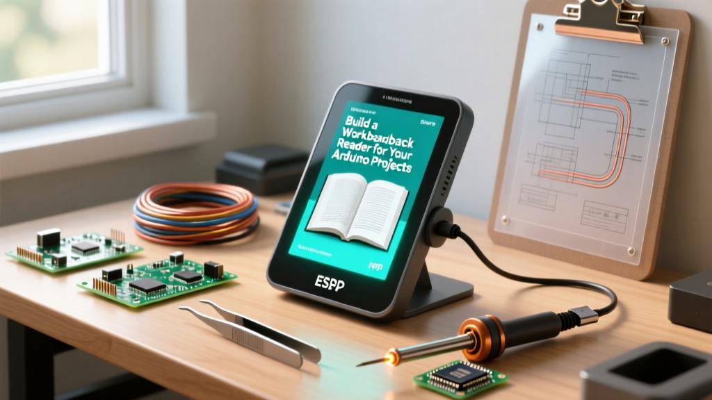
In this step-by-step tutorial, we will build a dedicated, splash-proof, low-cost 'Workbench PDF Reader.' This device is designed specifically to sit next to your soldering station and display the pages of your favorite arduino projects book pdf without the risk of catastrophic damage. By leveraging the ESP32 microcontroller, a 2.8-inch SPI TFT display, and a clever image-rasterization workaround, we can create a robust digital companion for under $22.
Hardware Bill of Materials (2026 Pricing)
Before we begin, gather the following components. Prices reflect average 2026 market rates from major distributors like DigiKey, Mouser, and reputable AliExpress vendors.
| Component | Specific Model / Part Number | Est. Price |
|---|---|---|
| Microcontroller | ESP32-WROOM-32 DevKit V1 (30-pin) | $6.50 |
| Display | 2.8' ILI9341 TFT SPI (320x240) | $11.00 |
| Storage | MicroSD Card Adapter Module (3.3V logic) | $1.50 |
| Media | 16GB MicroSD Card (Class 10) | $5.00 |
| Power | 5V 2A USB-C Power Supply | $4.00 |
| Misc | Jumper wires, tactile buttons, PETG filament | $3.00 |
Total Estimated Cost: $31.00 (or under $22 if sourcing generic SPI displays in bulk).
Step 1: The Rasterization Strategy (Crucial Architecture Decision)
Here is where most online tutorials fail. Beginners often search for an 'ESP32 PDF parser library.' Do not waste your time. The ESP32 has 520KB of internal SRAM. A single page of a modern arduino projects book pdf contains vector graphics, compressed font streams, and metadata that easily exceed 2MB. The ESP32 lacks the memory management unit (MMU) and raw RAM required to run robust C++ PDF rendering engines like MuPDF on bare metal.
The Expert Solution: We will rasterize (convert) the PDF pages into 320x240 JPEG images on our main computer, then load them onto the MicroSD card. The ESP32 will simply act as a high-speed image carousel.
- Install Python 3.10+ on your PC.
- Install the pdf2image library via pip:
pip install pdf2image. - Run a simple Python script to slice your arduino projects book pdf into sequentially named JPGs (e.g.,
page_001.jpg,page_002.jpg). - Copy the resulting image folder to the root directory of your FAT32-formatted MicroSD card.
Pro-Tip: Set the JPEG quality to 85% during conversion. This yields a file size of roughly 35KB per page, allowing a 16GB SD card to hold over 450,000 pages—more than enough for the entire Arduino documentation archive.
Step 2: Wiring the ESP32, TFT, and SD Card
Both the ILI9341 display and the MicroSD module use the SPI protocol. To save GPIO pins and maximize bus speed, we will share the SPI bus (MOSI, MISO, SCK) but use separate Chip Select (CS) pins.
Warning: Many cheap MicroSD modules sold online contain 5V level shifters that backfeed 5V into the ESP32's 3.3V MISO line, causing brownouts or permanent silicon damage. Ensure your SD module is strictly 3.3V native, or remove the onboard LDO and level-shifter ICs.
| ESP32 GPIO | ILI9341 TFT Pin | MicroSD Module Pin |
|---|---|---|
| 3V3 | VCC | 3.3V (or VCC) |
| GND | GND | GND |
| GPIO 18 (SCK) | SCL (or SCK) | SCK |
| GPIO 23 (MOSI) | SDA (or MOSI) | MOSI |
| GPIO 19 (MISO) | SDO (or MISO) | MISO |
| GPIO 15 | CS | - |
| GPIO 5 | - | CS |
| GPIO 2 | DC (Data/Command) | - |
| GPIO 4 | RESET | - |
Step 3: Configuring the TFT_eSPI Library
For driving the ILI9341, we rely on Bodmer's legendary TFT_eSPI library. It is heavily optimized for the ESP32's SPI DMA (Direct Memory Access) capabilities, allowing for flicker-free image rendering.
After installing the library via the Arduino IDE Library Manager, you must edit the User_Setup.h file located in the library's root folder. Uncomment and modify the following lines to match our wiring:
#define ILI9341_DRIVER
#define TFT_MISO 19
#define TFT_MOSI 23
#define TFT_SCLK 18
#define TFT_CS   15
#define TFT_DC    2
#define TFT_RST   4
#define SPI_FREQUENCY  40000000 // 40MHz is the sweet spot for ESP32-WROOM
Additionally, install the TJpg_Decoder library. This library decodes JPEGs line-by-line using a mere 3.5KB of RAM, entirely bypassing the need for PSRAM or massive heap allocations.
Step 4: The Firmware Logic
The firmware logic is straightforward but requires careful handling of the SD card initialization sequence. The ESP32's default SPI initialization can sometimes conflict with the TFT CS pin if not explicitly managed.
Core Loop Architecture
- Initialization: Boot sequence sets TFT_CS and SD_CS HIGH (deselected). Initialize TFT, then initialize SD.
- File Indexing: Scan the root directory for
.jpgfiles and store the filenames in an array or linked list. - Input Handling: Read two tactile buttons (Next Page / Previous Page) connected to GPIO 32 and GPIO 33 with internal pull-ups enabled.
- Rendering: When a button is pressed, call
TJpgDec.drawSdJpg(0, 0, currentPageFile). The DMA handles pushing the pixel data to the ILI9341 in the background, freeing the CPU to debounce the buttons.
By utilizing the ESP32's dual-core architecture, you can assign the JPEG decoding task to Core 0 while Core 1 handles the UI overlay (like a page number indicator in the bottom right corner).
Step 5: 3D Printing the Splash-Proof Enclosure
To truly protect your arduino projects book pdf viewer from the workbench environment, the enclosure must be robust. Do not use PLA filament; the ambient heat from a nearby Hakko FX-888D or Weller WE1010 soldering station can warp PLA over time.
Print Specifications:
- Material: PETG or ABS (PETG recommended for ease of printing and chemical resistance to flux).
- Dimensions: 115mm width x 80mm height x 30mm depth.
- Infill: 20% Gyroid for structural rigidity without wasting material.
- Design Feature: Include a 45-degree angled wedge base. This positions the screen at an optimal ergonomic viewing angle while standing at a workbench, and naturally deflects falling debris away from the SD card slot.
Troubleshooting Common Build Failures
Even with perfect wiring, SPI bus implementations on the ESP32 can present unique edge cases. Refer to this troubleshooting matrix if your build fails to boot.
| Symptom | Root Cause | Expert Fix |
|---|---|---|
| TFT displays pure white screen | SPI Frequency too high for the specific ILI9341 clone. | Lower SPI_FREQUENCY in User_Setup.h to 27000000 (27MHz). |
| SD Card fails to mount (Returns false) | CS pin conflict or 5V backfeed on MISO. | Verify SD module is 3.3V native. Ensure TFT_CS is set HIGH before calling SD.begin(). |
| JPEG decoding crashes ESP32 | Image resolution exceeds 320x240 or uses CMYK color space. | Ensure Python script forces RGB color space and strictly resizes to 320x240. |
| Flickering during page turns | DMA buffer underrun. | Increase the SPI DMA buffer size in the TFT_eSPI setup file. |
Final Thoughts on Workbench Ergonomics
Building a dedicated hardware reader for your arduino projects book pdf is more than just a fun weekend project; it is an investment in your workspace ergonomics and equipment longevity. By offloading the reference material to a $30 custom ESP32 kiosk, you keep your primary computing devices safe from the inevitable hazards of hardware prototyping. Furthermore, the skills learned here—specifically SPI bus sharing, DMA-driven rendering, and external storage management—are directly transferable to advanced IoT projects, such as smart home control panels and industrial telemetry displays.
For further reading on ESP32 hardware constraints and SPI routing, consult the official Espressif ESP32 DevKitC documentation. Happy building, and keep your soldering iron away from the screen!