
The Evolution of Arduino Starter Kit Projects in 2026
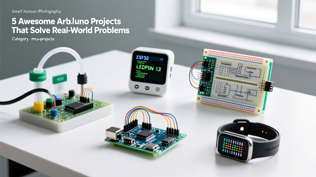
If you purchased an entry-level electronics bundle a few years ago, your first build was likely a blinking LED or a basic temperature reader on an LCD. Today, the landscape of arduino starter kit projects has fundamentally shifted toward the Internet of Things (IoT). As of 2026, premium starter kits (priced between $55 and $95) routinely include the Arduino Uno R4 WiFi, the Nano ESP32, or dedicated ESP32-S3 DevKits, completely bypassing the need for clunky external Wi-Fi modules like the ESP-01.
This hardware leap means beginners can now build robust, cloud-connected smart home devices right out of the box. In this guide, we will explore three high-value IoT builds you can execute using components found in modern IoT-focused starter kits, complete with wiring specifics, edge-case troubleshooting, and cloud integration strategies.
Hardware Matrix: What is in Your Kit?
Before diving into the builds, it is critical to identify the brain of your kit. The microcontroller dictates your logic levels, memory constraints, and IoT protocol capabilities.
| Microcontroller | Typical Kit Price (2026) | Logic Level | IoT Suitability | Common Failure Mode |
|---|---|---|---|---|
| Arduino Uno R4 WiFi | $85 - $95 | 5V | Excellent (Native Arduino IoT Cloud support) | Wi-Fi antenna detachment on breadboards |
| ESP32-WROOM-32 DevKit | $45 - $60 | 3.3V | Excellent (MQTT, Deep Sleep, ESP-NOW) | GPIO frying via 5V sensor backfeed |
| Arduino Nano ESP32 | $75 - $90 | 3.3V (5V tolerant RX/TX) | Superior (Compact, native Cloud support) | Bootloader corruption via USB-C hubs |
Project 1: Cloud-Connected Indoor Climate Node
Monitoring ambient temperature and humidity is a staple among arduino starter kit projects, but upgrading it to a cloud-logged dashboard provides real-world utility for server rooms, greenhouses, or humidors.
Components Required
- Arduino Uno R4 WiFi or ESP32 DevKit
- BME280 Sensor Module (I2C breakout)
- 4.7kΩ Pull-up Resistors (x2)
- Breadboard and jumper wires
Wiring and Logic Specifics
The BME280 communicates via I2C. While many tutorials simply tell you to connect VCC to 3.3V, GND to GND, SDA to SDA, and SCL to SCL, they often omit a critical hardware detail: I2C pull-up resistors.
- Connect the BME280 VCC to the 3.3V pin (never use 5V on a raw BME280 chip, or you will degrade the sensor's internal humidity membrane over time).
- If your breakout board lacks built-in pull-ups (common on sub-$3 clones), solder a 4.7kΩ resistor between SDA and 3.3V, and another between SCL and 3.3V.
- Check the I2C address. Most BME280 modules default to
0x76, but some use0x77. Run an I2C scanner sketch first to prevent silent initialization failures.
Cloud Integration
Using the Arduino IoT Cloud, create a 'Thing' with two float variables: temperature and humidity. Set the polling rate to 60 seconds. Polling faster than 30 seconds on a basic Wi-Fi router can trigger DHCP lease renewals or ARP table overflows, causing the device to drop off the network.
Project 2: Smart Wi-Fi Relay for AC Appliances
Controlling mains-powered devices is where IoT projects transition from toys to practical home automation. However, working with 120V/240V AC requires strict adherence to safety protocols.
Safety Warning: Never wire raw mains AC voltage directly to a breadboard. According to the National Electrical Code (NEC NFPA 70), all mains wiring must be properly enclosed, grounded, and strain-relieved. For this project, use a pre-enclosed smart plug teardown or a DIN-rail mounted relay module housed in a proper junction box.
The Optocoupler Isolation Rule
Your starter kit likely includes a 5V relay module. You must verify that the module features an optocoupler (typically a PC817 chip) between the logic input and the relay coil.
- Why it matters: When the relay coil de-energizes, it generates a massive back-EMF voltage spike. Without optical isolation and a flyback diode, this spike will travel back through the IN1 pin and instantly destroy your microcontroller's GPIO bank.
- Logic Level Shifting: If you are using an ESP32 (3.3V logic) but your relay module requires a 5V HIGH signal to trigger, you cannot connect them directly. Use a simple NPN transistor (like a 2N2222) or a logic level converter (TXS0108E) to bridge the 3.3V output to the 5V relay input.
Project 3: Ultrasonic Water Tank Level Monitor
For off-grid cabins or rainwater harvesting systems, knowing your tank level without walking outside is a game-changer. This project utilizes the HC-SR04 ultrasonic sensor and leverages the ESP32's deep sleep capabilities to run on batteries for months.
The 5V to 3.3V Echo Pin Trap
The HC-SR04 requires 5V to operate reliably and outputs a 5V signal on its Echo pin. If you wire a 5V Echo pin directly to a 3.3V ESP32 GPIO, you will slowly degrade the silicon until the pin shorts to VCC.
The Fix: Build a voltage divider on the Echo pin. Connect a 1kΩ resistor in series with the Echo output, and a 2kΩ resistor from the ESP32 GPIO to Ground. This safely drops the 5V signal down to approximately 3.33V.
Implementing Deep Sleep
Continuous Wi-Fi transmission will drain a 2000mAh LiPo battery in less than 48 hours. By utilizing the ESP32's Ultra-Low Power (ULP) co-processor and RTC timers, you can put the board to sleep and wake it only to take a measurement.
As detailed in the Espressif ESP32 Sleep Modes documentation, configuring the esp_sleep_enable_timer_wakeup() function allows the device to sleep for 15 minutes, wake up, connect to Wi-Fi, publish the distance payload via MQTT, and return to sleep in under 3 seconds. This reduces average power consumption from ~80mA to roughly 15µA, extending battery life to over 6 months.
Troubleshooting Common IoT Edge Cases
When transitioning from offline arduino starter kit projects to networked devices, you will encounter unique failure modes. Here is how to diagnose the most frequent issues:
1. The 'Brownout Detector' Reset Loop
Symptom: The ESP32 serial monitor spits out Brownout detector was triggered and reboots endlessly when the Wi-Fi radio initializes.
Cause: The Wi-Fi radio draws a transient spike of up to 500mA during TX bursts. If you are powering the board via a cheap USB cable with high resistance, or a 500mA PC USB port, the voltage drops below the 2.4V brownout threshold.
Solution: Use a high-quality, short USB-C cable rated for 3A, and plug it into a dedicated 5V/2A wall adapter. Alternatively, solder a 470µF electrolytic capacitor across the 5V and GND pins on the breadboard to act as a local energy reservoir.
2. MQTT Broker Disconnects on Router Reboot
Symptom: Your device connects to the MQTT broker (like Mosquitto or Adafruit IO) on boot, but if the home router restarts, the device never reconnects.
Cause: The Wi-Fi connection loop is often written in the setup() function. If the router is down during boot, the code either hangs infinitely or moves on to the loop() without an active IP address.
Solution: Implement a non-blocking Wi-Fi reconnect wrapper in your main loop(). Check WiFi.status() != WL_CONNECTED every 10 seconds and trigger a reconnection sequence. Furthermore, utilize the MQTT Last Will and Testament (LWT) feature so your dashboard accurately reflects when the device goes offline unexpectedly.
Final Thoughts on Kit Selection
The best arduino starter kit projects are those that solve actual problems in your environment. If your current kit only includes an Arduino Uno R3 (which lacks native networking), consider purchasing a standalone ESP32 DevKit V1 (usually under $8) and a BME280 sensor to bridge the gap into IoT. The skills you develop in handling logic-level shifting, I2C bus capacitance, and MQTT payload structuring will form the foundation of every advanced embedded system you build in the future.