
The Evolution of Arduino Electronics Projects in 2026
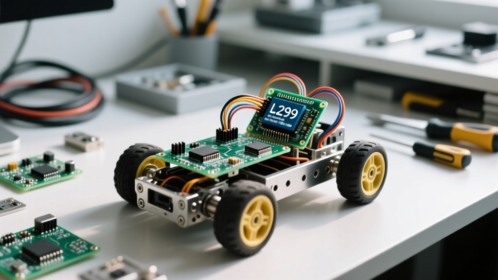
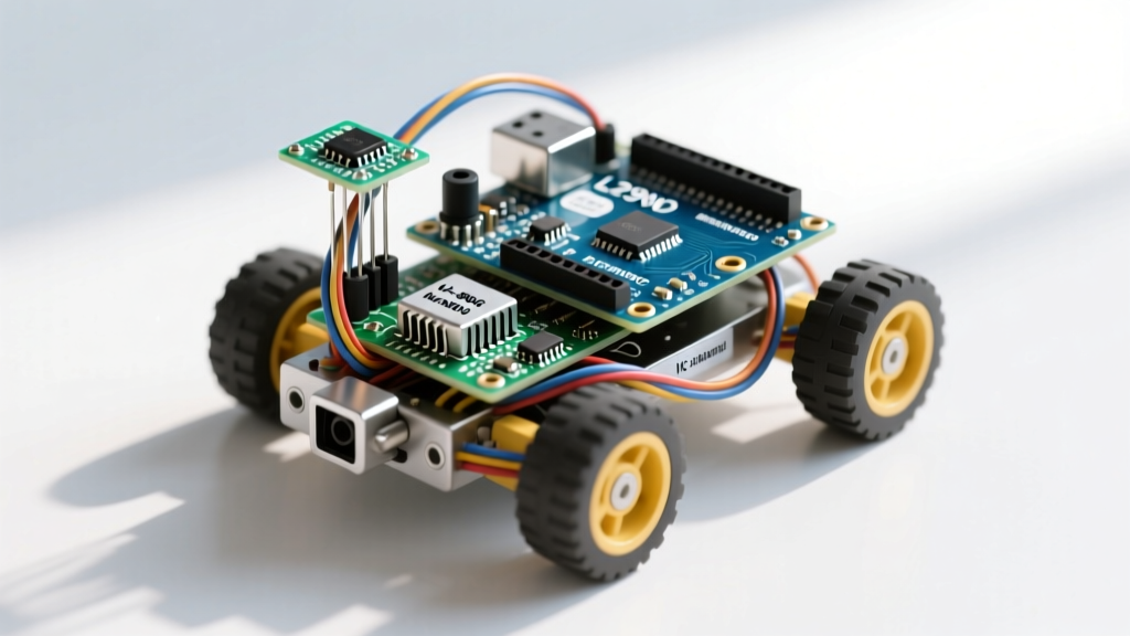
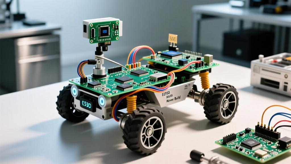
When evaluating advanced arduino electronics projects, the leap from simple line-followers to sensor-fused autonomous rovers requires a rigorous approach to power management, sensor fusion, and closed-loop control. In 2026, the availability of low-cost solid-state LiDAR and high-efficiency brushless motor drivers has completely transformed the hobbyist robotics landscape. However, the fundamental physics of power distribution and signal noise remain unchanged. This guide details the exact architecture, component selection, and failure-mode mitigation required to build a robust 4WD autonomous rover using the Arduino Mega 2560.
2026 Bill of Materials (BOM) for a 4WD Autonomous Rover
Selecting the right components is critical. Under-specifying your motor drivers or relying on the Arduino's onboard voltage regulator for logic power are the most common points of failure in intermediate arduino electronics projects. Below is the verified BOM for a high-torque, sensor-rich platform.
| Subsystem | Exact Component Model | Qty | 2026 Est. Price | Engineering Justification |
|---|---|---|---|---|
| Microcontroller | Arduino Mega 2560 Rev3 | 1 | $45.00 | 54 I/O pins and multiple hardware UARTs for LiDAR/GPS. |
| Motor Driver | BTS7960 43A High-Power Driver | 2 | $24.00 | Handles 4x TT motor stall currents (4.8A total) without thermal shutdown. |
| Sensors | TF-Luna LiDAR (8m) + MPU-6050 IMU | 1 ea | $26.00 | LiDAR provides reliable outdoor distance; IMU tracks chassis yaw/pitch. |
| Power Source | 3S LiPo 11.1V 2200mAh (40C) | 1 | $28.00 | High C-rating prevents voltage sag during 4-motor acceleration spikes. |
| Logic Regulator | LM2596 Step-Down Buck Converter | 1 | $4.50 | Steps 11.1V down to a clean 5V 3A for the Mega and sensors. |
| Chassis | Freenove 4WD Aluminum Alloy Kit | 1 | $38.00 | Metal chassis reduces flex, ensuring IMU readings aren't skewed by frame torsion. |
Power Architecture: Avoiding the Brownout Death Trap
The most frequent cause of spontaneous resets in robotics builds is improper power routing. When four TT gearmotors start simultaneously, they can draw up to 1.2A each, creating a momentary 4.8A current spike. If you power the Arduino Mega via the VIN pin or the barrel jack using the main battery, this spike will cause the onboard linear regulator to overheat and drop the logic voltage below 4.5V, triggering a brownout reset.
The Dual-Plane Power Solution
- Motor Power Plane: Connect the 11.1V LiPo main positive lead directly to the
B+terminals of both BTS7960 motor drivers. Connect the LiPo ground to theB-terminals. - Logic Power Plane: Wire the LiPo main leads into the input of the LM2596 buck converter. Adjust the potentiometer on the LM2596 until the output reads exactly 5.1V under no load. Connect this 5.1V output to the
5Vpin on the Arduino Mega (bypassing the onboard regulator entirely). - Common Ground: The ground from the LiPo, the buck converter output ground, and the Arduino
GNDpins must be tied together at a single central star point to prevent ground loops.
Expert Pro-Tip: Solder a 1000µF electrolytic capacitor and a 0.1µF ceramic capacitor in parallel across theB+andB-terminals of each BTS7960 driver. According to Pololu's motor driver design guidelines, this local decoupling absorbs high-frequency inductive kickback and low-frequency voltage sag, extending the lifespan of your driver MOSFETs.
Sensor Fusion: LiDAR and IMU Integration
Ultrasonic sensors (like the HC-SR04) are notorious for multipath errors and acoustic blindness outdoors. For a reliable 2026 rover, we use the TF-Luna LiDAR for forward obstacle detection and the MPU-6050 for dead-reckoning orientation.
Wiring the TF-Luna via Hardware UART
Software serial is too slow and interrupt-heavy for 115200 baud LiDAR streams. Wire the TF-Luna TX to the Mega's RX1 (Pin 19) and RX to TX1 (Pin 18). Power the LiDAR from the Mega's 5V pin (it draws only 70mA).
Stabilizing the I2C Bus for the MPU-6050
The MPU-6050 communicates via I2C. In arduino electronics projects involving motors, the PWM signals and brushed motor EMI (Electromagnetic Interference) frequently corrupt I2C data lines, resulting in NACK errors and frozen code.
- Connect MPU-6050
SDAto Mega Pin 20, andSCLto Pin 21. - Critical Step: Solder 4.7kΩ pull-up resistors between the
SDAline and 5V, and theSCLline and 5V. The internal Arduino pull-ups (approx. 30kΩ) are too weak to overcome motor EMI. - Keep the I2C wires under 15cm in length and route them away from the motor power cables.
Implementing Closed-Loop PID Motor Control
Open-loop PWM control is insufficient for autonomous navigation; battery voltage drop and terrain friction will cause the rover to drift. You must implement a PID (Proportional-Integral-Derivative) controller using encoder feedback.
While Texas Instruments' motor control literature heavily emphasizes digital signal processors for industrial PID, the Arduino Mega can comfortably handle a 50Hz PID loop for hobbyist rovers using the ArduinoPID library.
The Tuning Sequence
Do not attempt to guess PID values. Follow this strict tuning methodology:
- Step 1 (Proportional - P): Set I and D to zero. Increase P until the rover oscillates slightly around the target speed, then reduce it by 50%.
- Step 2 (Derivative - D): Increase D to dampen the oscillation. This acts as a predictive brake. Stop increasing D when motor noise (audible whining) begins.
- Step 3 (Integral - I): Slowly increase I to eliminate steady-state error (e.g., when the rover is slightly underpowered on an incline). Keep I as low as possible to prevent integral windup.
Real-World Troubleshooting Matrix
Even with perfect wiring, edge cases will emerge during field testing. Use this diagnostic matrix to resolve common anomalies found in complex arduino electronics projects.
| Observed Failure Mode | Root Cause Analysis | Hardware / Software Fix |
|---|---|---|
| Mega resets when motors engage | Voltage sag on the 5V logic rail due to shared ground impedance. | Implement a star-ground topology; add 1000µF bulk capacitance to the buck converter output. |
| MPU-6050 freezes after 5 minutes | I2C bus lockup caused by EMI from brushed TT motors. | Add 4.7kΩ hardware pull-ups; implement a software watchdog timer to reset the I2C bus. |
| Rover drifts left/right on flat ground | Open-loop PWM; manufacturing variance in TT gearmotors. | Install magnetic encoders on the rear wheels and enable closed-loop PID velocity control. |
| TF-Luna reads 0cm randomly | UART buffer overflow due to blocking code in the main loop. | Use a non-blocking state machine; parse LiDAR packets only when Serial1.available() >= 9. |
Final Assembly and Field Testing
Before deploying the rover outdoors, conduct a "tethered test." Elevate the chassis on blocks, connect the Arduino to your PC via USB (for serial debugging), and power the motors via the LiPo. Verify that the LiDAR distance readings stabilize within ±2cm and that the PID controller corrects wheel speed discrepancies within 200 milliseconds of a manual load disturbance.
By treating power distribution as a primary engineering constraint rather than an afterthought, you elevate your builds from fragile prototypes to robust, field-ready machines. For deeper insights into microcontroller pinout configurations and hardware serial limits, always consult the official Arduino Mega 2560 documentation before finalizing your PCB or perfboard layout.