
Why the 2WD Rover is the Ultimate Starting Point
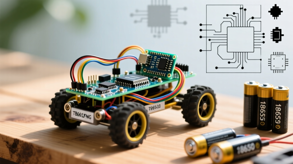
When makers search for easy Arduino projects, they are often met with blinking LEDs or basic temperature loggers. While useful, these lack the kinetic satisfaction of robotics. Building a 2-Wheel Drive (2WD) obstacle-avoiding rover bridges the gap between basic microcontroller programming and real-world electromechanical engineering. It introduces differential steering, sensor fusion, and power management without requiring a degree in kinematics.
In this guide, we will bypass the outdated, high-friction L298N motor drivers found in cheap 2015-era kits and utilize modern, efficient components to build a rover that actually works on carpet and hardwood alike.
Bill of Materials (BOM) & Component Selection
Choosing the right hardware prevents 90% of the frustration associated with beginner robotics. Below is the optimized 2026 BOM for a reliable 2WD rover.
| Component | Specific Model / Spec | Est. Cost (2026) | Why We Chose It |
|---|---|---|---|
| Microcontroller | Arduino Uno R4 Minima | $27.50 | 32-bit ARM Cortex-M4, 48MHz. Overkill for basic logic, but future-proofs your build for PID control loops. |
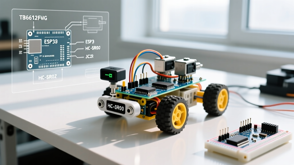
| Motor Driver | TB6612FNG Breakout | $11.95 | MOSFET-based H-bridge. Drops only ~0.5V compared to the 2V drop of legacy BJT-based L298N drivers. |
| Sensors | HC-SR04 Ultrasonic (x1) | $2.50 | 40kHz transducer. Reliable up to 400cm with a practical blind spot of <2cm. |
| Motors | TT Gearmotors (1:48 ratio) | $4.00 / pair | Standard yellow hobby motors. Stall current is ~800mA, well within the TB6612FNG's 1.2A continuous limit. |
| Power Supply | 2x 18650 Li-ion (e.g., Samsung 25R) + Holder | $18.00 | 7.4V nominal. Provides high current delivery without the severe voltage sag seen in 6x AA alkaline packs. |
Mechanical Assembly: Avoiding the Caster Wheel Trap
Most generic acrylic chassis kits include a metal ball caster wheel. While fine on smooth tile, the metal ball creates immense rolling resistance on carpet, causing the TT gearmotors to stall and draw maximum current, which triggers brownouts.
The Omni-Wheel Upgrade
Replace the standard ball caster with a plastic omni-wheel or a 3D-printed caster fitted with a PTFE (Teflon) insert. This reduces the coefficient of friction dramatically. When mounting the TT motors, use M3x10mm screws with nylon locknuts. The vibration from the 1:48 plastic gears will strip standard nuts off the acrylic chassis within 20 minutes of operation if not secured properly.
Wiring Matrix and Power Distribution
Power distribution is where most easy Arduino projects fail when scaled to robotics. You must separate the high-current motor paths from the sensitive logic paths.
- Motor Power (VM): Connect the 18650 battery pack positive terminal directly to the TB6612FNG
VMpin. - Logic Power (VCC): Connect the Arduino's 5V output to the TB6612FNG
VCCpin. - Grounding: Tie the battery ground, motor driver ground, and Arduino ground together at a single star-ground point to prevent ground loops.
Pinout Mapping
| Arduino Uno R4 Pin | TB6612FNG / Sensor Pin | Function |
|---|---|---|
| D5 (PWM) | PWMA | Left Motor Speed Control |
| D4 | AIN1 | Left Motor Direction 1 |
| D7 | AIN2 | Left Motor Direction 2 |
| D6 (PWM) | PWMB | Right Motor Speed Control |
| D8 | BIN1 | Right Motor Direction 1 |
| D9 | BIN2 | Right Motor Direction 2 |
| D10 | STBY | Driver Standby (Pull HIGH) |
| D11 | HC-SR04 Trigger | Ultrasonic Pulse Out |
| D12 | HC-SR04 Echo | Ultrasonic Pulse In |
Control Logic: Beyond Simple If/Else
While a basic if (distance < 20) { turn(); } loop works, it results in a jittery, chaotic robot. To achieve smooth navigation, implement a simple state machine with PWM ramping.
Pro Tip: Do not use the raw
pulseIn()function for the HC-SR04 if your robot is moving fast.pulseIn()is a blocking function that halts the Arduino while waiting for the echo, causing the motors to coast unpredictably. Use the Arduino Timer Interrupts or the non-blockingNewPinglibrary to read the sensor asynchronously while maintaining continuous PID motor control.
The Speed of Sound Calculation
The HC-SR04 measures the time it takes for a 40kHz acoustic wave to bounce back. At 20°C, sound travels at roughly 343 meters per second. The formula to convert the microsecond duration into centimeters is:
distance_cm = (duration_us * 0.0343) / 2;
We divide by 2 because the sound wave travels to the obstacle and back.
Troubleshooting Common Failure Modes
Even with the best components, physics and electrical noise will test your patience. Here are the most common edge cases and their exact fixes.
1. The "Brownout Reset" Spin
Symptom: The robot moves forward, hits an obstacle, attempts to turn, and suddenly the Arduino restarts (pin 13 LED flashes).
Root Cause: When both TT motors stall or start under heavy load, they can draw up to 1.6A combined. If your battery has high internal resistance, the voltage drops below the Arduino's brownout detection threshold (usually ~2.7V for the ATmega/RA4M1), causing a reset.
The Fix: Solder 100µF electrolytic capacitors directly across the terminals of each TT motor to suppress inductive voltage spikes. Furthermore, ensure your 18650 cells are high-discharge rated (like the Samsung 25R or Sony VTC6), not cheap laptop-pull cells with high internal resistance.
2. Ultrasonic "Ghost" Readings
Symptom: The serial monitor occasionally spits out 0 cm or 4000 cm when an object is clearly 30 cm away.
Root Cause: Acoustic cross-talk or soft surfaces. If the robot is near a corner, the 40kHz wave bounces multiple times, exceeding the 38ms timeout window. Alternatively, fabrics like curtains absorb the acoustic energy entirely.
The Fix: Implement a median filter in your code. Take 5 rapid readings, discard the highest and lowest, and average the remaining three. This eliminates 99% of acoustic anomalies.
3. The "Circle of Death"
Symptom: You command the robot to drive straight, but it veers heavily to the left or right.
Root Cause: Manufacturing tolerances in cheap TT gearmotors mean one motor will naturally spin 5-10% faster than the other at the exact same PWM value.
The Fix: You must calibrate a steering offset in your code. If it pulls left, reduce the PWM value of the right motor by roughly 15 points (e.g., Left = 200, Right = 185) until the chassis tracks perfectly straight.
Next Steps: Expanding Your Robotics Platform
Once your 2WD rover reliably navigates your living room, you have a robust platform for more advanced experiments. Consider upgrading the single HC-SR04 to a servo-mounted ultrasonic sensor for 180-degree spatial mapping, or swap the Arduino Uno R4 for an ESP32-S3 to stream telemetry data via Wi-Fi to a local MQTT broker. Mastering these easy Arduino projects builds the foundational muscle memory required for complex, multi-agent robotic swarms.