
The Enduring Appeal of Arduino Uno Projects in Modern Robotics
As of 2026, the landscape of microcontroller development has expanded with powerful ARM-based boards and AI-capable edge devices. Yet, when engineers and educators search for foundational Arduino Uno projects, the classic ATmega328P-based board remains the undisputed gold standard for learning robotics. Its 5V logic tolerance, robust DIP packaging, and massive library ecosystem make it the perfect brain for a differential-drive mobile robot.
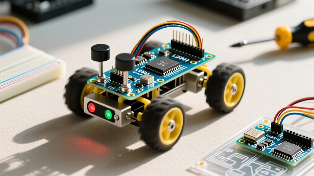
In this comprehensive build guide, we move beyond basic LED blinking. We will engineer a fully functional 2-Wheel Drive (2WD) obstacle avoidance robot. This build emphasizes real-world engineering constraints: managing inductive motor noise, mitigating power supply brownouts, and writing non-blocking C++ firmware. According to the official Arduino Uno R3 documentation, the board's 14 digital I/O pins and 6 PWM channels are perfectly suited for motor control and ultrasonic sensor integration, provided you architect your power delivery correctly.
Bill of Materials (BOM) and Component Selection
Selecting the right components is where most beginner robotics builds fail. We are prioritizing torque, voltage stability, and sensor reliability over the cheapest possible alternatives.
| Component | Specific Model / Spec | Est. Price (2026) | Engineering Rationale |
|---|---|---|---|
| Microcontroller | Arduino Uno R3 (ATmega328P) | $27.50 | 5V logic natively interfaces with standard ultrasonic sensors without level shifters. |
| Motor Driver | L298N Dual H-Bridge Module | $5.50 | Handles up to 2A per channel. Includes onboard 5V regulator for the Arduino. |
| Drive Motors | TT Gearmotors (1:48 ratio, 3-6V) | $8.00 (pair) | High torque at low RPM. Adafruit's Motor Selection Guide recommends these for light indoor chassis. |
| Rangefinder | HC-SR04 Ultrasonic Sensor | $2.50 | 40kHz transducers provide reliable 2cm to 400cm ranging with minimal CPU overhead. |
| Sensor Pan | SG90 9g Micro Servo | $3.50 | Allows left/right scanning without requiring the entire chassis to rotate. |
| Power Supply | 2S 18650 LiPo Holder + Cells | $22.00 | 7.4V nominal (8.4V peak). Low internal resistance prevents voltage sag under load. |
| Chassis | Acrylic 2WD Base + Caster Wheel | $11.00 | Low center of gravity; metal ball caster reduces friction compared to plastic skids. |
Power Architecture: Avoiding the 9V Battery Trap
The most common failure mode in entry-level Arduino Uno projects is the use of 9V alkaline batteries. A standard 9V battery has a high internal resistance (often exceeding 500 milliohms). When your TT gearmotors stall or start up, they can draw upwards of 1.2A each. According to Ohm's Law, this current spike causes a massive voltage drop across the battery's internal resistance, triggering a brownout on the Arduino's ATmega328P chip and causing erratic sensor readings or complete system resets.
The LiPo Solution
For this build, we use a 2S (2-cell series) 18650 Lithium-Ion battery pack. A fully charged 2S pack outputs 8.4V, dropping to 7.4V nominally. Furthermore, the L298N motor driver utilizes bipolar junction transistors (BJTs) which introduce a voltage drop of approximately 2V to 2.5V. As detailed in the Pololu Motor Driver Selection Guide, this means your 8.4V LiPo pack will deliver roughly 6.4V to the motors at peak charge—perfectly aligning with the 6V maximum rating of the TT motors, while the 5V onboard regulator of the L298N cleanly steps down the voltage to power the Arduino Uno's VIN pin.
Pro-Tip: Never wire the 5V output of the L298N directly to the Arduino's "5V" pin if the Arduino is also connected to a PC via USB. This creates a back-feeding conflict that can destroy the USB interface IC. Always connect the L298N 5V out to the Arduino's "VIN" or "Barrel Jack" input.
Wiring Matrix and Pinout Allocation
Efficient pin management ensures you leave room for future upgrades, such as adding IR line-tracking sensors or a gyroscope. Below is the exact wiring schema for this build.
| Arduino Uno Pin | Target Component | Function / Notes |
|---|---|---|
| Digital 2 | HC-SR04 Echo | Receives 5V pulse width corresponding to distance. |
| Digital 3 | HC-SR04 Trigger | Sends 10µs pulse to initiate ultrasonic burst. |
| Digital 5 (PWM) | L298N ENA | Controls Left Motor speed via PWM. |
| Digital 4 | L298N IN1 | Left Motor Direction A. |
| Digital 7 | L298N IN2 | Left Motor Direction B. |
| Digital 6 (PWM) | L298N ENB | Controls Right Motor speed via PWM. |
| Digital 8 | L298N IN3 | Right Motor Direction A. |
| Digital 9 | L298N IN4 | Right Motor Direction B. |
| Digital 10 (PWM) | SG90 Servo Signal | PWM control for ultrasonic sensor panning. |
Firmware Logic: Non-Blocking Sensor Pings
A critical mistake in many Arduino Uno projects is using the delay() function to wait for the robot to move or for the servo to sweep. In a moving robot, a 500ms delay means the robot travels blindly for half a second, guaranteeing collisions at high speeds.
Instead, we implement a state-machine architecture using the millis() function. This allows the Arduino to continuously poll the HC-SR04 sensor while simultaneously adjusting motor PWM values.
Handling the HC-SR04 Timeout Edge Case
The standard pulseIn() function will hang the microcontroller indefinitely if the ultrasonic echo is absorbed by soft materials (like curtains or foam) and never returns. To prevent this, always use the three-argument version of the function:
long duration = pulseIn(echoPin, HIGH, 30000); // 30ms timeoutIf the timeout is reached, duration returns 0. Your logic must explicitly handle a 0 return value as an "out of bounds" or "error" state, defaulting to a halt-and-scan maneuver rather than driving forward.
Mechanical Assembly and Center of Gravity
When mounting the 2S 18650 battery pack, place it as close to the drive axle as possible, directly between the two TT motors. The front caster wheel acts as a pivot. If the battery is mounted too far forward, the caster will bear too much weight, increasing rotational friction and causing the robot to drag during turns. If mounted too far back, the front end will lift, causing the robot to "wheelie" during rapid acceleration, which blinds the HC-SR04 sensor by pointing it at the ceiling.
Troubleshooting Common Robotics Failure Modes
Even with perfect wiring, real-world physics introduces edge cases. Here is how to diagnose the most frequent issues encountered in this specific build:
- Issue: Motors emit a high-pitched whine but do not spin.
Diagnosis: The PWM signal from the Arduino is too low to overcome the static friction (stiction) of the TT motor gears, but high enough to vibrate the coils.
Solution: Implement a "kickstart" routine in your code. When transitioning from a stop to a move, send a 100% PWM signal for 50 milliseconds to break stiction, then drop to your desired cruising speed (e.g., PWM 160). - Issue: HC-SR04 returns erratic, impossibly short distances (e.g., 2cm) when motors are running.
Diagnosis: Electromagnetic interference (EMI) and voltage ripple from the brushed DC motors are corrupting the 5V logic rail, causing false triggers on the Echo pin.
Solution: Solder a 0.1µF ceramic decoupling capacitor directly across the VCC and GND pins on the HC-SR04 sensor board. Additionally, ensure the motor power ground and logic ground are tied together at a single "star ground" point on the chassis to prevent ground loops. - Issue: Robot veers to the left or right when told to drive straight.
Diagnosis: Manufacturing tolerances in cheap TT gearmotors mean they rarely draw the exact same current or spin at the exact same RPM at identical PWM values.
Solution: Calibrate a steering bias in your code. If the robot pulls left, reduce the right motor PWM by an offset value (usually between 5 and 15) until straight-line travel is achieved. For advanced builders, integrating a BNO055 IMU to create a closed-loop PID heading controller is the ultimate fix.
Final Thoughts on Scaling Your Build
Mastering power delivery, non-blocking code, and sensor noise mitigation transforms a simple toy into a robust robotic platform. Once this 2WD obstacle avoidance logic is stable, the Arduino Uno's remaining I/O pins allow you to easily integrate an MPU6050 accelerometer for dead-reckoning, or swap the L298N for a more efficient TB6612FNG MOSFET-based driver to eliminate the 2V voltage drop and extend your LiPo battery runtime by up to 30%. The foundation laid by these core Arduino Uno projects will serve as the bedrock for every advanced autonomous system you build in the future.