
The Case for a Standalone DIY Arduino in Home Automation
When most makers begin their home automation journey, they reach for a fully assembled Arduino Uno or Mega. While excellent for prototyping on a workbench, deploying a bulky $27 development board inside a permanent wall junction box or DIN rail enclosure is highly inefficient. By 2026, the smart home standard demands compact, low-cost, and highly reliable nodes. This is where the DIY Arduino approach shines.
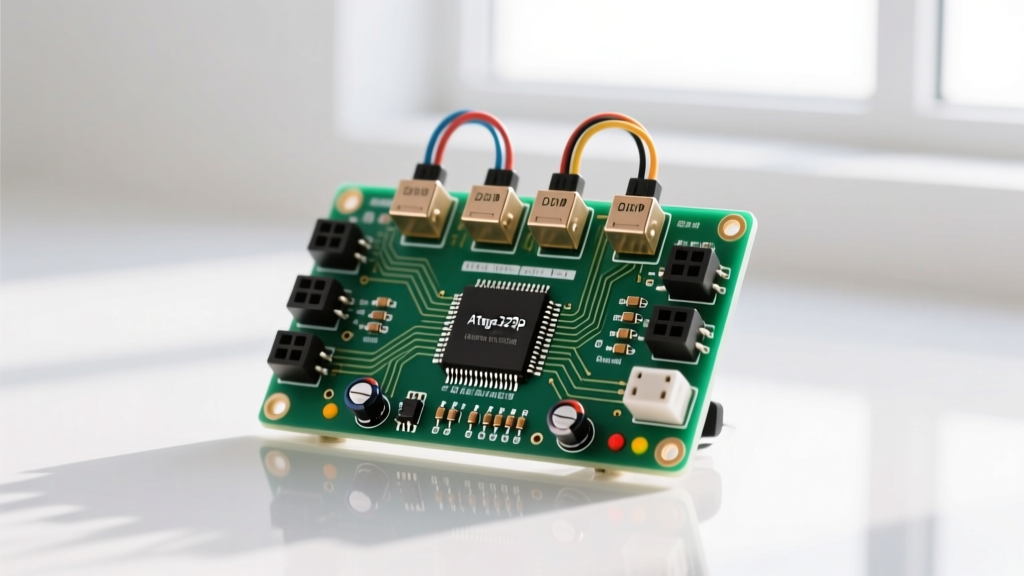
By building a standalone ATmega328P-PU circuit on a custom perfboard or printed circuit board (PCB), you strip away the unnecessary USB-to-serial chips, voltage regulators, and LEDs found on commercial boards. This reduces the footprint by over 80%, drops the microcontroller cost to under $3, and eliminates the parasitic power draw of onboard debugging LEDs. In this guide, we will engineer a robust, 4-channel DIY Arduino smart relay hub capable of controlling mains-powered lighting and HVAC dampers, bridging the gap between raw electronics and professional home automation.
Bill of Materials (BOM) and 2026 Cost Breakdown
Sourcing components in small quantities has become highly streamlined. Below is the exact BOM required to build the logic and switching core of the hub. Prices reflect average 2026 market rates from major distributors like Digi-Key and Mouser.
| Component | Specification / Model | Qty | Est. Cost (2026) |
|---|---|---|---|
| Microcontroller | ATmega328P-PU (DIP-28) | 1 | $2.85 |
| Crystal Oscillator | 16.000 MHz HC49S | 1 | $0.45 |
| Load Capacitors | 22pF Ceramic (C1, C2) | 2 | $0.10 |
| Relay Module | 4-Channel 5V SRD-05VDC-SL-C | 1 | $4.20 |
| Step-Down Converter | LM2596 Buck Module (5V Out) | 1 | $1.65 |
| IoT Wi-Fi Bridge | ESP-01S (ESP8266) | 1 | $2.10 |
| Passives | 10kΩ, 1kΩ, 2kΩ Resistors, 100nF Caps | Kit | $0.50 |
| Total Estimated Build Cost | $11.85 | ||
Designing the Minimal ATmega328P Circuit
To transition from a standard Arduino board to a true DIY Arduino setup, you must replicate the minimal operating circuit. The ATmega328P-PU requires very few external components to run reliably at 16 MHz. According to the official Arduino Standalone Guide, the core requirements revolve around clock stability and reset pin management.
Critical Decoupling and Reset Pinouts
Failure to properly decouple the power pins is the number one cause of erratic behavior in standalone home automation nodes. Mains switching generates massive electromagnetic interference (EMI). You must place a 100nF (0.1µF) ceramic capacitor as physically close to the microcontroller pins as possible on the following pairs:
- VCC (Pin 7) to GND (Pin 8)
- VCC (Pin 20) to GND (Pin 22)
- AVCC (Pin 21) to GND (Pin 22) - Even if you are not using the analog-to-digital converter (ADC), AVCC must be tied to 5V with its own decoupling cap to stabilize the internal logic thresholds.
For the reset pin (Pin 1/PC6), a 10kΩ pull-up resistor to VCC is mandatory. Without it, the pin floats, and EMI from the relay coils will induce random voltage spikes, causing the microcontroller to spontaneously reboot while your house lights are on.
The Power Supply Trap: Why Linear Regulators Fail
A common and catastrophic mistake in DIY Arduino home automation projects is using an LM7805 linear voltage regulator to step down a 12V wall adapter to 5V. Let us look at the math for a 4-channel relay hub paired with an ESP-01S Wi-Fi module.
Each SRD-05VDC-SL-C relay coil draws approximately 71mA. Four relays equal 284mA. The ESP-01S can draw up to 170mA during Wi-Fi transmission spikes. The ATmega328P draws roughly 20mA. Your total 5V system current is ~475mA.
If you drop 12V to 5V across an LM7805 at 475mA, the regulator must dissipate 3.3 Watts of heat ( (12V - 5V) * 0.475A ). Without a massive, enclosure-breaking heatsink, the LM7805 will hit its thermal shutdown threshold at 150°C within seconds of the relays engaging, dropping your entire home automation node offline.
The Solution: Use an LM2596 switching buck converter. Switching regulators operate at 85% to 92% efficiency. The same 475mA load will generate less than 0.4 Watts of heat, keeping the system ice-cold and entirely reliable inside a sealed DIN-rail enclosure.
Integrating IoT: Bridging to ESP-01 via UART
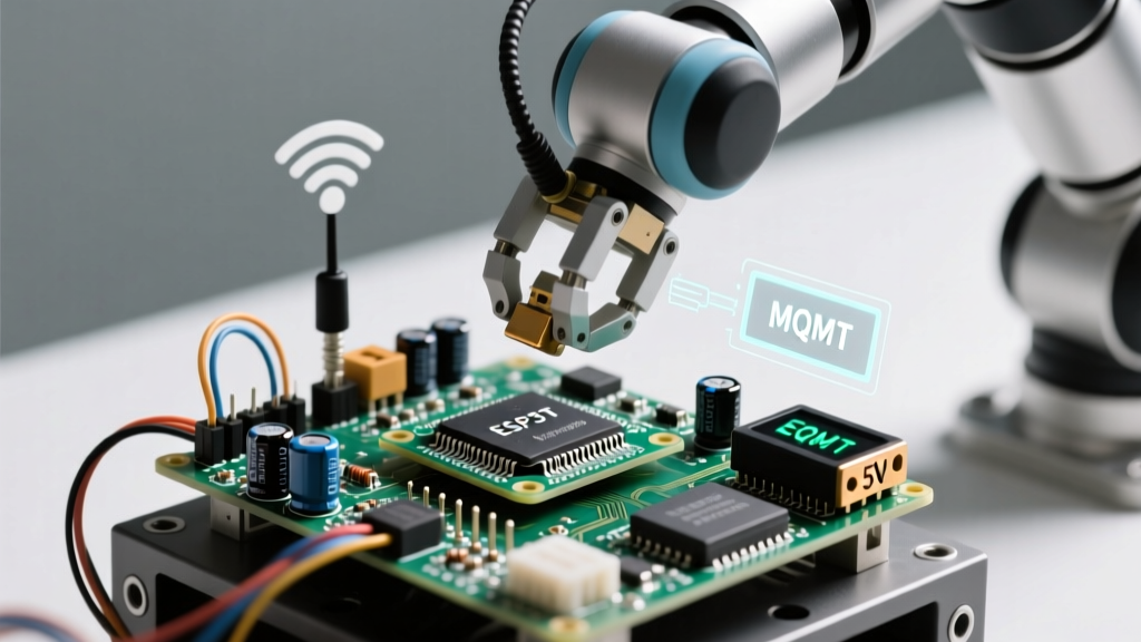
A home automation hub is useless if it cannot communicate with your central server (like Home Assistant or Node-RED). We use the ESP-01S as a dedicated Wi-Fi UART bridge. The ATmega328P handles the real-time relay logic and debouncing, while the ESP-01S handles the heavy MQTT protocol lifting.
Connect the ESP-01S TX pin to the ATmega328P RX pin (Pin 0). However, the ATmega328P operates at 5V logic, and the ESP-01S RX pin is strictly 3.3V tolerant. Feeding 5V directly into the ESP-01S will degrade the silicon over time, leading to eventual Wi-Fi failure. You must build a simple voltage divider using a 1kΩ and 2kΩ resistor to drop the ATmega's 5V TX signal down to a safe ~3.3V for the ESP-01S RX pin.
Firmware Architecture and Relay Debounce Logic
When writing the firmware for your DIY Arduino, avoid using delay() functions. Home automation requires instant responsiveness to physical wall switches and network commands simultaneously. Implement a non-blocking state machine using millis().
Furthermore, mechanical wall switches connected to the ATmega328P digital inputs suffer from contact bounce. A single physical toggle can register as 15 rapid on/off transitions in a span of 5 milliseconds. Implement a software debounce routine that requires the pin state to remain stable for at least 50 milliseconds before committing the state change to the relay output pins. For an in-depth look at managing inductive loads and relay logic, refer to the SparkFun Relay Tutorial.
Mains Voltage Safety and NEC Compliance
Interfacing low-voltage microcontrollers with 120V/240V AC mains is inherently dangerous. In the United States, all permanent wiring installations must adhere to the National Electrical Code (NEC). Specifically, NFPA 70 (NEC) Article 720 and Article 404 dictate strict separation between low-voltage control circuits and high-voltage power circuits.
WARNING: Never route 5V DC logic traces parallel to 120V AC mains traces on the same PCB without a routed isolation gap and physical earth-grounded shield. Always house the relay module in a fire-retardant ABS or polycarbonate enclosure, and use proper wire nuts or Wago connectors for all AC splices. If you are not certified to work with mains voltage, hire a licensed electrician to handle the AC wiring.
Troubleshooting Common Edge Cases
Even with perfect schematics, real-world home automation environments introduce noise and edge cases. Here is how to diagnose the most frequent DIY Arduino failures:
- Relay Chatter / Humming: If your relays rapidly click on and off, your 5V power rail is browning out. The inrush current of the relay coil is pulling the voltage below the ATmega328P's brown-out detection (BOD) threshold (usually 2.7V or 4.3V). Add a 470µF electrolytic capacitor directly across the 5V and GND rails near the relay module to supply instantaneous current.
- ESP-01S Wi-Fi Drops: The ESP8266 is highly sensitive to voltage ripple. If the LM2596 buck converter has high switching noise, the ESP-01S will drop its MQTT connection. Solder a 10µF ceramic capacitor directly across the VCC and GND pins of the ESP-01S module itself.
- Optocoupler Failure on Relay Boards: Many cheap 4-channel relay modules feature an 'optocoupler' but leave the JD-VCC jumper intact, defeating the purpose of galvanic isolation. To protect your DIY Arduino from mains voltage spikes traveling back through the relay coil, remove the JD-VCC jumper, and power the relay coil side with a completely separate 5V source, tying only the control ground to the microcontroller ground via the optocoupler's internal LED.
By moving away from expensive development boards and engineering a purpose-built DIY Arduino node, you create a home automation system that is not only vastly more affordable but significantly more robust and tailored to the exact electrical demands of your living space.