
The Hidden Power Drain in Standard Arduino Boards
When makers begin exploring simple Arduino projects, the classic Arduino Uno is almost always the starting point. However, if your goal is energy-efficient design for off-grid or battery-powered IoT nodes, the standard Uno is fundamentally flawed. An unmodified Arduino Uno draws roughly 50mA of current while active and idles at around 15mA. This quiescent drain is not caused by the ATmega328P microcontroller itself, but by the peripheral components soldered to the board.
The onboard LM7805 linear voltage regulator wastes significant power as heat when stepping down battery voltage. Furthermore, the USB-to-serial converter chip (usually an ATmega16U2 or CH340G) constantly draws current, and the onboard power LED burns through roughly 3mA to 5mA continuously. For a project powered by a standard 2000mAh 18650 lithium cell, an unmodified Uno will die in less than 48 hours, even if the microcontroller is put to sleep.
To build truly energy-efficient simple Arduino projects that run for months or years on standard batteries, you must rethink both your hardware selection and your software architecture.
Selecting the Right Microcontroller for Battery Life
The foundation of any low-power build is choosing a board designed for efficiency. Below is a comparison of popular development boards and their real-world power profiles as of 2026.
| Microcontroller Board | Active Current | Sleep/Deep Sleep Current | Best Use Case |
|---|---|---|---|
| Arduino Uno R3 | ~50 mA | ~15 mA (Idle) | Desktop prototyping only |
| Arduino Pro Mini (3.3V/8MHz) | ~4 mA | ~0.005 mA (Modded) | Ultra-low power sensor nodes |
| ESP32-WROOM-32 DevKit | ~240 mA (Wi-Fi TX) | ~0.010 mA (Deep Sleep) | Wi-Fi/BLE IoT data transmission |
| Adafruit Feather 32u4 | ~10 mA | ~0.050 mA | LoRaWAN and portable wearables |
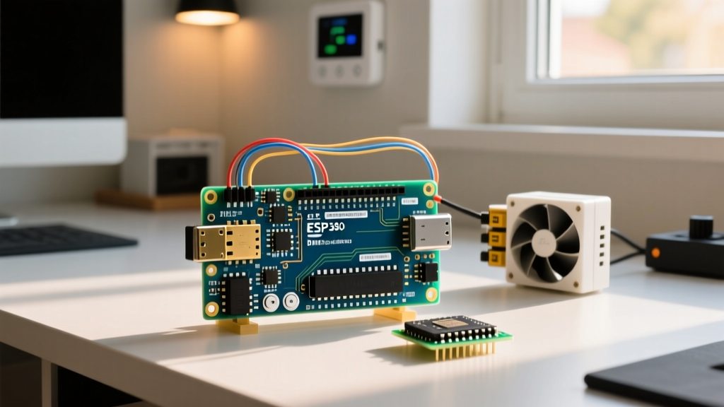
For basic environmental logging, the 3.3V/8MHz Arduino Pro Mini remains a legendary choice. By removing the power LED and bypassing the onboard regulator, you can achieve micro-amp sleep currents. For projects requiring wireless telemetry, the ESP32 is mandatory, provided you utilize its specialized deep sleep co-processor (ULP).
Hardware Modifications for Ultra-Low Quiescent Current
Before writing a single line of sleep code, you must address hardware-level parasitic drains. Here are the critical modifications for energy-efficient simple Arduino projects:
- Remove Power LEDs: Desolder the red or green power indicator LEDs and their associated current-limiting resistors. This alone can save 3mA to 10mA of continuous drain.
- Bypass Linear Regulators: If using a Pro Mini or raw ATmega328P chip, do not use linear LDOs to step down from 3x AA batteries (4.5V) to 3.3V. Instead, use a high-efficiency switching buck/boost regulator like the Pololu S7V8A. Switching regulators maintain >90% efficiency across varying loads, whereas linear regulators waste the voltage differential as heat.
- Use Capacitive Over Resistive Sensors: Standard resistive soil moisture sensors draw up to 30mA and suffer from rapid galvanic corrosion. Switch to Capacitive Soil Moisture Sensor v1.2 modules, which draw only ~5mA during active reads and do not corrode in wet soil.
- Implement High-Side Switching: Use a P-channel MOSFET (like the SI2301) to completely cut power to external sensors and voltage dividers when the microcontroller is asleep. This prevents phantom current from leaking through sensor modules.
Software Strategies: Mastering Sleep Modes
The ATmega328P and ESP32 handle power states very differently. Understanding these architectural differences is crucial for maximizing battery life in your simple Arduino projects.
Implementing Watchdog Timers on ATmega328P
On AVR-based boards, you cannot simply pause the code; you must put the CPU into a specific hardware sleep state. The most effective method is using the Watchdog Timer (WDT) to wake the chip periodically. The industry-standard Rocketscream Low-Power library simplifies this process.
By calling LowPower.powerDown(SLEEP_8S, ADC_OFF, BOD_OFF);, you shut down the Analog-to-Digital Converter and the Brown-Out Detector (BOD). Disabling the BOD in software is a critical, often-missed step. Leaving the BOD enabled during sleep will draw an extra 15µA to 20µA. With BOD off, a raw ATmega328P chip draws roughly 5µA (0.005mA) in power-down mode.
Deep Sleep on ESP32 for IoT Sensor Nodes
The ESP32 architecture relies on an RTOS (Real-Time Operating System). Standard delay functions do not save power; they merely yield the CPU. To achieve the ~10µA deep sleep current, you must configure the Espressif Sleep Modes API to wake via a timer or external interrupt.
Expert Tip: When using ESP32 deep sleep, all RAM data is lost upon waking. You must use the
RTC_DATA_ATTRattribute to store critical state variables (like boot counts or accumulated sensor readings) in the Real-Time Clock memory, which remains powered during deep sleep.
Real-World Project: The 2-Year Soil Moisture Monitor
Let us apply these principles to a practical, energy-efficient build: an off-grid garden soil moisture monitor that transmits data via LoRa once every 4 hours.
Component Selection and Power Budget
- MCU: Raw ATmega328P-PU (DIP-28 package) running at 8MHz internal clock, 3.3V.
- Radio: RFM95W LoRa Transceiver (Sleep current: 0.2µA).
- Sensor: Capacitive Soil Moisture v1.2 (Active current: 5mA).
- Power Source: 2x Standard Panasonic Eneloop AA batteries (1900mAh total). We choose standard Eneloops over the higher-capacity Eneloop Pros because standard cells have a significantly lower self-discharge rate, which is the limiting factor in multi-year micro-amp projects.
Calculating Battery Life
The system wakes up every 4 hours (6 times a day). The active cycle takes exactly 2 seconds: 1 second to power the sensor via MOSFET, 0.5 seconds to read the ADC, and 0.5 seconds to transmit a 12-byte LoRa payload at 14dBm (~45mA TX current).
Average Current Draw Calculation:
- Active phase (2 seconds): Average 20mA. (20mA * 2s) = 40mAs per cycle.
- Sleep phase (14,398 seconds): Total system sleep draw is 15µA (0.015mA). (0.015mA * 14398s) = 215.97mAs per cycle.
- Total mAs per 4-hour cycle: 255.97mAs.
- Daily consumption: 255.97 * 6 = 1535.82mAs = 0.426mAh per day.
With a 1900mAh battery capacity and accounting for a 20% loss due to self-discharge over time, the theoretical battery life is over 10 years. In reality, environmental temperature fluctuations and battery chemistry degradation will likely cap this at 4 to 5 years, which is still an astonishing achievement for such simple Arduino projects.
Troubleshooting Common Low-Power Failures
Even with perfect code, hardware edge cases can ruin your power budget. If your multimeter shows higher-than-expected sleep currents, check these common failure modes:
- Floating Input Pins: A GPIO pin configured as an INPUT that is left unconnected (floating) will pick up electromagnetic noise. This causes the internal CMOS logic gates to oscillate rapidly, drawing milliamps of phantom current. Fix: Tie all unused pins to GND, or enable internal pull-up resistors via software.
- I2C Bus Leakage: If you are using I2C sensors, the pull-up resistors on the SDA and SCL lines can leak current through the sensor's internal protection diodes when the MCU is asleep. Fix: Power the I2C sensors from a switched GPIO pin rather than the main VCC rail, ensuring the sensor is completely unpowered during sleep.
- USB-to-Serial Backpowering: If you leave an FTDI programmer connected to your Pro Mini while measuring sleep current, the programmer will backpower the board through the TX/RX lines. Fix: Always disconnect programming adapters before taking quiescent current measurements.
By combining rigorous hardware selection, parasitic drain elimination, and precise sleep-state programming, you can transform basic microcontroller experiments into robust, energy-efficient simple Arduino projects capable of surviving years in the field without human intervention.