
The Role of Expressive Lighting in Modern Robotics
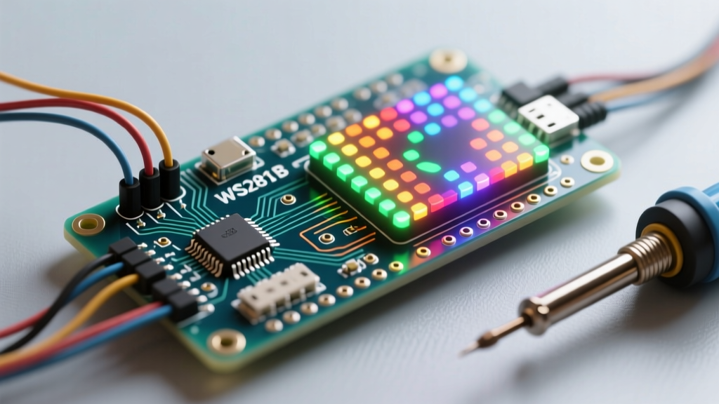
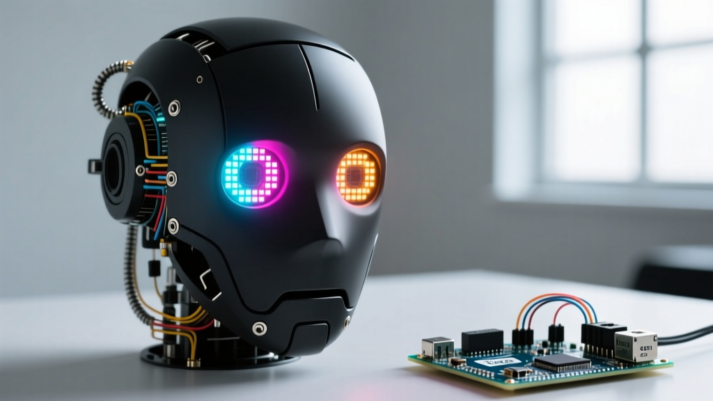
In the realm of autonomous robotics, Human-Robot Interaction (HRI) relies heavily on non-verbal cues. While servos and motors provide movement, lighting systems communicate internal states, intentions, and emotional proxies to human operators. When engineers and makers explore arduino projects led lights integrations, they frequently default to simple status indicators. However, advanced rover builds demand high-resolution, addressable LED matrices that can render expressive 'eyes' and dynamic navigation feedback without interrupting the robot's core sensor-fusion loops.
This comprehensive build guide details the engineering, power management, and non-blocking firmware architecture required to integrate an 8x8 WS2812B NeoPixel matrix into an Arduino-based autonomous rover. We will bypass the common beginner pitfalls—such as logic-level mismatching and brownout resets—and focus on production-grade reliability for mobile robotics.
Component Selection: Matrix Topologies Compared
Not all addressable LEDs are created equal, especially when mounted on a vibrating, power-constrained mobile chassis. Selecting the right silicon is the first critical step in any advanced robotics lighting build.
| LED IC Protocol | Refresh Rate / PWM | Wiring Complexity | Best Robotics Use Case | Approx. 2026 Cost (8x8) |
|---|---|---|---|---|
| WS2812B | 400Hz / 8-bit | 3-pin (5V, GND, Data) | Expressive eyes, low-speed status rings | $12.00 - $15.00 |
| APA102 (DotStar) | 20kHz / 8-bit | 4-pin (5V, GND, Data, Clock) | High-speed persistence-of-vision (POV) wheels | $28.00 - $35.00 |
| SK6812 (RGBW) | 400Hz / 8-bit | 4-pin (5V, GND, Data, VCC) | Illumination-heavy builds requiring pure white | $18.00 - $22.00 |
For an expressive robot face, the WS2812B remains the undisputed champion of cost-to-performance. Its 400Hz refresh rate is imperceptible to the human eye during standard rover operation, and the 3-pin architecture minimizes cabling through the robot's pan/tilt neck joints.
Hardware Architecture & 2026 BOM
To ensure the LED matrix does not starve the microcontroller or interfere with I2C LiDAR sensors, we must isolate the power domains while maintaining signal integrity. Below is the precise Bill of Materials (BOM) for this build, reflecting current 2026 market pricing for authentic components.
- Microcontroller: Arduino Nano 33 IoT ($21.50) - Chosen for its compact footprint, native 3.3V logic, and integrated IMU for head-tracking.
- LED Matrix: 8x8 WS2812B 5050 Flexible Matrix ($14.00) - 64 pixels total.
- Logic Level Shifter: 74AHCT125 Quad Buffer ($1.20) - Critical for 3.3V to 5V data translation.
- Power Supply: 5V 5A Step-Down Buck Converter (LM2596 based) ($6.50) - To handle peak matrix current.
- Capacitor: 1000µF 10V Electrolytic Capacitor ($0.45).
- Wiring: 18 AWG Silicone Wire for power rails; 26 AWG stranded for data lines.
Power Management: The 3.84A Bottleneck
The most frequent cause of failure in arduino projects led lights builds is inadequate power provisioning. A single WS2812B pixel drawing maximum white (RGB all on at 255) consumes approximately 60mA.
Critical Calculation: 64 pixels × 0.060A = 3.84 Amps peak current draw.
Attempting to power this matrix via the Arduino Nano's 5V pin (which is typically limited to 500mA via USB or 1A via the onboard regulator) will instantly trigger thermal shutdown or melt the board's PCB traces.
Solution: Wire the 5V 5A buck converter directly to the robot's main 12V LiPo battery. Route the 5V output directly to the matrix's VCC and GND pads using 18 AWG silicone wire. Thinner wires (like 22 AWG or standard jumper wires) will introduce voltage drop over the length of the robot's neck, causing the furthest pixels to shift from white to yellow or red due to undervoltage.
Furthermore, as detailed in the Adafruit NeoPixel Uberguide, you must place a 1000µF electrolytic capacitor across the VCC and GND terminals of the matrix. This acts as a local energy reservoir, absorbing the initial inrush current when the LEDs are commanded to full brightness and preventing voltage sags that could reset the Arduino's brownout detector (BOD).
Logic Level Shifting: Why 3.3V Fails at 800kHz
Modern robotics heavily favor 3.3V microcontrollers to interface safely with 3.3V sensors (like the BNO055 IMU or VL53L1X Time-of-Flight sensors). The Arduino Nano 33 IoT operates at 3.3V. However, the WS2812B data sheet specifies a minimum logic high voltage (VIH) of 0.7 × VDD. With a 5V supply, the data line must reach at least 3.5V to be reliably read as a '1'.
Feeding a 3.3V data signal directly into a 5V WS2812B matrix will result in erratic flickering, random color shifts, and complete signal degradation. While some makers attempt to use simple NPN transistors or MOSFETs for level shifting, these components often lack the switching speed required for the WS2812B's strict 800kHz data protocol.
The 74AHCT125 Fix: This specific IC is designed with TTL-compatible thresholds. It will reliably interpret the Nano's 3.3V output as a logic HIGH and switch its output to a clean, sharp 5V signal capable of driving the data line at high frequencies without edge-rounding. Wire the Nano's D6 pin to the 74AHCT125 input, and the IC output to the matrix DIN pad.
Non-Blocking Firmware for Autonomous Rovers
In a mobile robot, the main loop() must continuously poll ultrasonic sensors, calculate PID loops for motor control, and read IMU data. Using the standard delay() function to animate LED eyes will freeze the robot's brain, causing it to crash into obstacles while it finishes a 'blink' animation. As emphasized in the official Arduino Non-Blocking Code documentation, time-based operations must be decoupled from the execution flow.
We utilize the FastLED Library, which includes the powerful EVERY_N_MILLISECONDS macro. This allows us to update the matrix state only when required, leaving the rest of the CPU cycles free for navigation.
Implementation Architecture
#include <FastLED.h>
#define LED_PIN     6
#define NUM_LEDS    64
CRGB leds[NUM_LEDS];

// State machine variables
uint8_t currentExpression = 0;
unsigned long lastBlinkTime = 0;

void setup() {
  FastLED.addLeds<WS2812B, LED_PIN, GRB>(leds, NUM_LEDS);
  FastLED.setBrightness(40); // Limiting global brightness to 1.5A max for thermal safety
}

void loop() {
  // 1. Run Motor PID & Sensor Fusion (Non-blocking)
  navigateRobot();

  // 2. Update LED States without delaying the loop
  updateRobotEyes();

  FastLED.show();
}

void updateRobotEyes() {
  EVERY_N_MILLISECONDS(30) {
    // Animate pupil tracking based on IMU tilt data
    shiftPupilMatrix(getIMUPitch(), getIMURoll());
  }

  EVERY_N_SECONDS(4) {
    // Execute a natural, randomized blink sequence
    triggerBlinkAnimation();
  }
}
By structuring the code this way, the FastLED.show() command pushes the framebuffer to the matrix in roughly 1.9 milliseconds (64 pixels × 24 bits / 800kHz), ensuring the robot's odometry is never starved of processing time.
Diagnostic Matrix: Troubleshooting Visual Artifacts
When integrating high-speed addressable lighting into electrically noisy robotics environments (where DC motors generate massive EMI), you will inevitably encounter visual artifacts. Use this diagnostic matrix to isolate the root cause.
| Symptom | Probable Cause | Engineering Solution |
|---|---|---|
| Random pixels flashing neon green/pink | EMI noise from motor drivers corrupting the 800kHz data signal. | Route data wire away from motor power lines. Add a 470Ω resistor in series on the DIN line close to the matrix. |
| First pixel works, rest are dead or flickering | Missing or broken DOUT to DIN daisy-chain solder joint. | Reflow solder on the output pad of the first pixel; check for pad lift-off due to chassis vibration. |
| Colors shift from White to Yellow/Red at the edges | Voltage drop across the matrix PCB copper traces. | Inject 5V power into both the top and bottom rows of the 8x8 matrix (dual-end power injection). |
| Entire matrix freezes during motor acceleration | Brownout reset on the Arduino Nano due to shared ground bounce. | Implement a star-ground topology. Connect battery GND, Motor Driver GND, and Arduino GND at a single central bus bar. |
Conclusion
Integrating expressive lighting into autonomous platforms elevates a project from a mere collection of sensors to an engaging, communicative entity. By respecting the electrical realities of the WS2812B protocol—specifically regarding peak current provisioning, high-speed logic level translation, and EMI mitigation—you ensure that your arduino projects led lights build remains robust enough for real-world robotics competitions and long-term autonomous deployment.