
Beyond Blinking LEDs: The Reality of Modern Robotics
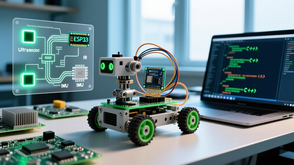
When engineers and makers transition from basic desktop prototypes to real-world autonomous rovers, they quickly discover that standard tutorials fall short. In 2026, building a reliable autonomous robot requires moving past simple delay() loops and basic threshold logic. To create truly responsive machines, we must architect robust, non-blocking systems capable of processing multiple sensor streams simultaneously. This is where advanced arduino code projects separate themselves from hobbyist toys, leveraging finite state machines, sensor fusion, and precise power management to navigate unpredictable environments.
In this guide, we will break down the exact hardware, software architecture, and edge-case troubleshooting required to build a sensor-fused autonomous navigation rover using the Arduino ecosystem.
The Hardware Bottleneck: Selecting the Right Microcontroller
Many legacy arduino code projects rely on the ATmega328P (Uno) or ATmega2560 (Mega). While excellent for learning, their limited SRAM and clock speeds become severe bottlenecks when running high-frequency PID loops, UART-based LiDAR parsing, and I2C multiplexing simultaneously. For a modern autonomous build, stepping up to a 32-bit ARM Cortex-M7 board is virtually mandatory.
| Board | Processor | SRAM | Clock Speed | Approx. Price | Best Use Case |
|---|---|---|---|---|---|
| Arduino Uno R4 Minima | Renesas RA4M1 (Cortex-M4) | 32 KB | 48 MHz | $20 USD | Basic line-followers, single-sensor avoidance |
| Arduino Mega 2560 | ATmega2560 (8-bit AVR) | 8 KB | 16 MHz | $45 USD | High I/O count, low-speed mechanical arms |
| Arduino GIGA R1 WiFi | STM32H747XI (Dual Core M7/M4) | 512 KB + 8MB SDRAM | 480 MHz | $85 USD | Sensor fusion, ROS 2 micro-ROS, complex SLAM |
For this build, we are utilizing the Arduino GIGA R1 WiFi. Its dual-core architecture allows us to offload high-speed sensor polling (like I2C Time-of-Flight arrays) to the M4 core, while the M7 core handles the primary navigation state machine and wireless telemetry. You can review the full hardware capabilities on the official GIGA R1 documentation page.
Architecting the Control Loop: Non-Blocking State Machines
The most common failure mode in intermediate robotics builds is the blocking control loop. If your robot stops to scan the environment using a servo-mounted ultrasonic sensor, a blocking delay() function halts all motor updates, encoder polling, and telemetry. This results in a robot that is blind and deaf to its own momentum while scanning.
Implementing a Finite State Machine (FSM)
To solve this, we implement a Finite State Machine. Instead of linear code, the robot transitions between discrete states based on environmental triggers. Our primary states include:
- STATE_CRUISE: Forward motion with active PID correction for straight-line tracking.
- STATE_OBSTACLE_DETECTED: Triggered when TF-Luna LiDAR reads < 40cm. Motors halt, scanning begins.
- STATE_SCANNING: Non-blocking servo sweep. The M4 core polls VL53L1X sensors and builds a local occupancy array.
- STATE_EVADE: Calculates the vector with the highest clearance and executes a differential turn.
By relying on the Arduino millis() function for time-tracking, we can execute the servo sweep incrementally. The code checks if a specific millisecond interval has passed, moves the servo one degree, updates the sensor reading, and immediately returns to the main loop to poll wheel encoders. This guarantees that motor PID updates occur every 10 milliseconds, regardless of the scanning state.
Sensor Fusion: Combining LiDAR and Time-of-Flight Arrays
Ultrasonic sensors (like the HC-SR04) suffer from acoustic scattering and wide beam angles, making them unreliable for precise gap detection in cluttered environments. Modern robotics builds utilize a hybrid approach:
- Primary Distance: TF-Luna LiDAR (UART, 8m range, 250Hz polling rate) mounted on a pan-tilt servo for long-range vector mapping.
- Peripheral Blind-spot Detection: Three VL53L1X Time-of-Flight sensors (I2C, 4m range) angled at -45°, 0°, and +45° to catch low-hanging obstacles that the LiDAR's elevated beam might miss.
Solving the I2C Address Collision
The VL53L1X sensors all share the same default I2C address (0x29). To use multiple sensors on the same bus, you have two options: sequentially change their addresses using the XSHUT pins during boot, or use an I2C multiplexer like the TCA9548A. For rapid development and robust isolation, the TCA9548A is preferred. It prevents SDA/SCL line capacitance issues from locking up the bus—a notorious edge case in robotics where long wiring runs introduce parasitic capacitance, causing I2C ACK failures and hard-locking the microcontroller.
Power Delivery: Managing High-Current Edge Cases
A critical aspect often ignored in software-focused arduino code projects is power topology. A 4WD rover utilizing four 12V DC gearmotors can draw upwards of 8 Amps under stall conditions. If the logic circuit and the motor drivers share the same voltage regulator, the moment the motors engage, a massive voltage sag (brownout) will reset the Arduino GIGA, corrupting the I2C bus and wiping the SLAM memory.
The Isolated Power Topology
We utilize a 3S LiPo battery (11.1V nominal, 12.6V fully charged) as the primary energy source. The power is split at the main distribution board:
- Motor Rail (11.1V): Fed directly into dual Pololu TB6612FNG motor drivers. These drivers handle up to 1.2A continuous per channel (3.2A peak) and feature built-in flyback diodes to suppress inductive kickback from the DC motors.
- Logic Rail (5V): Stepped down using a Murata OKI-78SR-5/1.5-W36-C switching regulator. Unlike linear regulators (like the L7805) which dissipate excess voltage as heat and fail under high differentials, this switching regulator operates at 90% efficiency, providing a clean, isolated 5V/1.5A rail exclusively for the GIGA R1, LiDAR, and I2C multiplexer.
Troubleshooting Matrix: Common Robotics Failures
Even with perfect code, hardware edge cases will disrupt autonomous navigation. Below is a diagnostic matrix for the most common failures encountered during field testing.
| Failure Symptom | Root Cause | Hardware / Code Solution |
|---|---|---|
| Arduino randomly reboots during sharp turns | Voltage brownout caused by motor current spikes exceeding the BEC (Battery Eliminator Circuit) limits. | Separate logic and motor power rails. Add a 4700µF low-ESR capacitor across the motor driver VMOT pins. |
| I2C sensors freeze after 10 minutes of operation | Parasitic capacitance on long SDA/SCL lines causing signal degradation and missed ACK bits. | Use a TCA9548A multiplexer to isolate buses. Keep I2C traces under 30cm and add 4.7kΩ pull-up resistors. |
| Robot drifts to the left despite straight code commands | Manufacturing tolerances in DC gearmotors cause varying RPMs at the same PWM voltage. | Implement closed-loop PID control using quadrature encoders. Tune the 'P' (Proportional) gain to correct differential drift. |
| LiDAR returns erratic '0' distance readings | UART buffer overflow due to blocking code preventing the serial read loop from clearing the buffer fast enough. | Move UART parsing to the M4 core using hardware serial interrupts and a ring buffer data structure. |
Summary and Next Steps
Building an autonomous rover requires a holistic approach that bridges mechanical design, electrical engineering, and advanced software architecture. By upgrading to a dual-core board like the GIGA R1 WiFi, implementing non-blocking finite state machines, and isolating your power rails, you elevate your build from a fragile prototype to a robust, field-ready machine. As you expand your arduino code projects portfolio, consider integrating micro-ROS (Robot Operating System) over WiFi to enable real-time SLAM (Simultaneous Localization and Mapping) visualization on a remote dashboard, pushing the boundaries of what is possible within the Arduino ecosystem.