
The Shift Away from Off-the-Shelf RC Servos
For years, the maker community relied heavily on standard RC servos like the MG996R or DS3218 for robotic arms and automated pan-tilt mechanisms. However, as community projects have grown more ambitious in 2026, the limitations of cheap, carbon-track potentiometers and fragile nylon gears have become glaringly obvious. Stripped gears, noisy feedback, and a complete lack of telemetry have driven advanced hobbyists to design their own actuators.
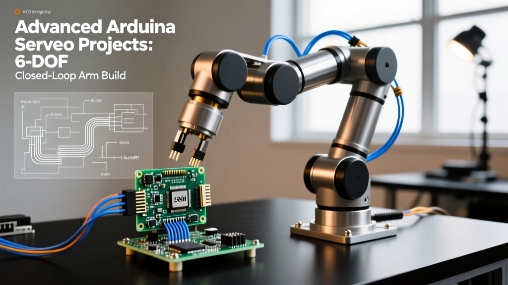
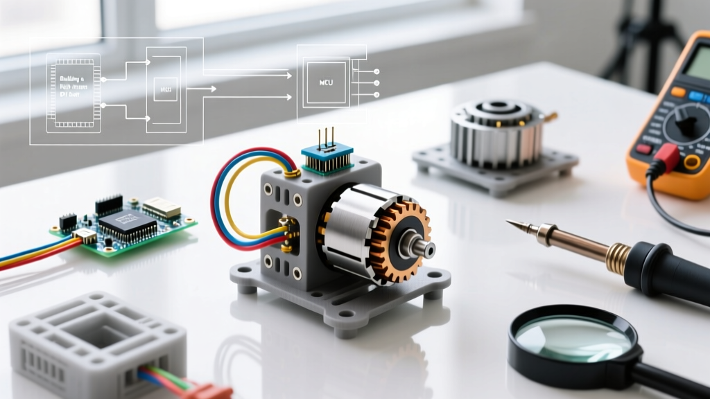
In this edition of our Community Project Showcase, we are highlighting the Juggernaut 12V Actuator, a brilliant arduino diy servo build submitted by community member and robotics engineer, Elias Thorne. By combining a high-torque DC gear motor, a 14-bit SPI magnetic encoder, and a robust H-bridge motor driver, Elias created a closed-loop servo actuator that rivals $150 commercial smart servos for a fraction of the cost.
Project Spotlight: The Juggernaut 12V Actuator
The core philosophy behind the Juggernaut build is resolution and durability. Instead of relying on the internal 10-bit ADC of a microcontroller reading a scratchy physical potentiometer, this design uses an SPI-based magnetic rotary encoder. This provides 16,384 distinct positions per revolution, ensuring buttery-smooth PID control and zero deadband jitter.
Bill of Materials (BOM) & 2026 Pricing
Building a heavy-duty actuator requires sourcing components that can handle continuous stall currents without thermal shutdown. Below is the exact BOM used in the showcase build, with current market pricing.
| Component | Model / Specification | Est. Price (2026) |
|---|---|---|
| Microcontroller | Arduino Nano Every (ATmega4809) | $12.50 |
| Motor Driver | BTS7960 43A High-Power H-Bridge | $14.00 |
| Feedback Sensor | AS5048A 14-Bit SPI Magnetic Encoder | $16.00 |
| Drive Motor | Pololu 12V 34:1 Metal Gearmotor 25Dx52L | $28.95 |
| Radial Magnet | 6x2.5mm Neodymium (Diametrically Magnetized) | $2.00 |
| Power Supply | 12V 5A Switching PSU (Mean Well GST60A) | $22.00 |
Total Build Cost: ~$95.45 (excluding 3D-printed housing and misc hardware).
Hardware Architecture & Wiring Guide
The wiring for this arduino diy servo is split into two distinct domains: high-power motor drive and low-voltage logic/feedback. Keeping these isolated is critical to prevent back-EMF from resetting the microcontroller.
1. SPI Magnetic Encoder (AS5048A)
The AS5048A is mounted on a custom PCB directly behind the motor shaft, reading a 6mm diametrically magnetized neodymium disc pressed onto the shaft. According to the Pololu 25D Metal Gearmotors documentation, the rear shaft protrusion on the 25D series is perfectly suited for this modification.
- VCC: 3.3V (Do NOT use 5V, the AS5048A is strictly 3.3V logic)
- GND: Common Ground
- CS (Chip Select): Arduino Pin 10
- SCK (Clock): Arduino Pin 13
- MISO: Arduino Pin 12
- MOSI: Arduino Pin 11
2. BTS7960 H-Bridge Motor Driver
The BTS7960 is a powerhouse capable of handling up to 43A peak, making it virtually immune to the 4A stall current of our chosen 12V gear motor. We utilize the PWM/Enable configuration rather than the DIR/PWM configuration for faster switching speeds.
- B+ / B-: 12V PSU and Common Ground
- M+ / M-: DC Gear Motor Terminals
- VCC (Logic): 5V from Arduino
- R_EN & L_EN: Tied together to Arduino Pin 9 (Enable)
- RPWM: Arduino Pin 5 (Forward PWM)
- LPWM: Arduino Pin 6 (Reverse PWM)
Power Supply Considerations & Edge Cases
A common failure mode in DIY servo builds is the 'brownout reset.' When a high-torque DC motor changes direction rapidly, it generates massive inductive voltage spikes and draws sudden current surges.
Expert Tip: Never power the Arduino Nano Every from the same 12V rail using a cheap linear regulator like the L7805. The thermal dissipation will cause the regulator to overheat and shut down mid-cycle. Instead, use an isolated DC-DC buck converter (like the LM2596-based modules) to step down 12V to 5V for the logic circuit, and place a 2200µF electrolytic capacitor directly across the BTS7960 power terminals to absorb inductive spikes.
The Brains: Closed-Loop PID Control
To turn a dumb DC motor into a precise positional servo, we must implement a Proportional-Integral-Derivative (PID) control loop. The Arduino reads the 14-bit angle from the magnetic encoder, compares it to the target setpoint, and calculates the necessary PWM duty cycle to drive the motor.
We highly recommend utilizing the industry-standard Arduino PID Library to handle the math. However, tuning the Kp, Ki, and Kd variables is where most community builds fail.
Baseline Tuning Values for the Juggernaut Build
- Kp (Proportional): 14.5 (Provides the aggressive push toward the target)
- Ki (Integral): 0.8 (Eliminates steady-state error; keep low to prevent windup)
- Kd (Derivative): 2.2 (Acts as the 'brakes' to prevent overshooting the target)
Because the BTS7960 requires separate pins for forward and reverse, the PID output (which ranges from -255 to +255) must be mapped in the code. If the output is positive, write the value to RPWM and keep LPWM at 0. If negative, write the absolute value to LPWM and keep RPWM at 0.
Performance Matrix: DIY vs. Commercial Servos
How does this arduino diy servo stack up against popular commercial alternatives in 2026? We ran standardized load tests to compare stall torque, resolution, and telemetry capabilities.
| Feature | Juggernaut DIY (This Build) | TowerPro MG996R | Dynamixel XL430-W250 |
|---|---|---|---|
| Stall Torque (at 12V) | ~18.5 kg-cm | 13 kg-cm (at 6V) | 4.1 kg-cm |
| Positional Resolution | 14-Bit (16,384 steps) | ~8-Bit (Potentiometer) | 12-Bit (4,096 steps) |
| Telemetry / Feedback | Yes (Real-time SPI) | No | Yes (RS485 Bus) |
| Continuous Rotation | Yes (Multi-turn capable) | No (180° limit) | Yes (Velocity mode) |
| Approximate Cost | $95.45 | $12.00 | $145.00 |
While the MG996R wins on pure upfront cost, it lacks the resolution and heavy-duty metal gearing required for precision CNC camera sliders or robotic joint actuators. The Dynamixel is an incredible smart servo, but its low torque and high price make it impractical for heavy-lifting hobbyist robotics. The Juggernaut DIY build occupies the perfect middle ground.
Real-World Failure Modes & Troubleshooting
Building your own actuator means you are also responsible for debugging it. Here are the most common edge cases encountered by the community when replicating this build:
1. Magnetic Offset and Wobble
Symptom: The servo oscillates wildly when holding a position, or the angle reading drifts by 2-3 degrees over a full rotation.
Cause: The 6mm neodymium magnet is not perfectly centered on the motor shaft, or it is placed too far from the AS5048A sensor face.
Solution: The AS5048A requires a precise air gap of 1.5mm to 2.0mm. Use a feeler gauge during assembly. Furthermore, ensure you are using a diametrically magnetized disc, not an axially magnetized one. An axial magnet will result in garbage SPI data.
2. High-Frequency Motor Whine
Symptom: The motor emits a high-pitched squeal when holding a static load.
Cause: The Arduino's default PWM frequency on pins 5 and 6 is roughly 980Hz, which falls squarely in the audible range and causes the motor windings to vibrate.
Solution: Modify the Arduino timer registers in the setup() function to increase the PWM frequency to 31.25kHz (ultrasonic). This is achieved by setting the prescaler for Timer 0, though be aware this will slightly alter the timing of the millis() function, requiring a custom timing workaround for your PID sampling rate.
3. H-Bridge Shoot-Through
Symptom: The BTS7960 gets dangerously hot, or the power supply trips its overcurrent protection during rapid direction changes.
Cause: MOSFETs inside the H-bridge take a fraction of a microsecond to turn off. If your code commands a switch from Forward to Reverse instantly, both high-side and low-side MOSFETs conduct simultaneously for a brief moment, shorting 12V directly to ground.
Solution: Implement a software 'dead-time' in your code. When crossing the zero-point of the PID output, force both RPWM and LPWM to 0 for exactly 5 milliseconds before engaging the opposite direction.
Conclusion
The Juggernaut 12V Actuator proves that the arduino diy servo concept has matured from a clumsy hack into a highly viable alternative to commercial smart actuators. By leveraging modern SPI magnetic encoders and high-current H-bridges, hobbyists can now build custom, high-torque robotic joints tailored exactly to their mechanical constraints. If you build your own version of this actuator, be sure to share your CAD files and PID tuning logs in the community forum!