
The Core Component Matrix: Choosing Your Brain
Before diving into specific Arduino beginner project ideas for robotics, you must select the right microcontroller. While the classic Uno R3 is ubiquitous, the newer Uno R4 Minima offers a 32-bit ARM Cortex-M4 processor, vastly improving computational overhead for inverse kinematics and PID loops. Selecting the right board prevents bottlenecks when your robot needs to process sensor fusion data in real-time.
| Microcontroller | Processor | Flash/SRAM | Price (2026) | Best For |
|---|---|---|---|---|
| Arduino Uno R3 | ATmega328P (8-bit) | 32KB / 2KB | $27.00 | Simple bang-bang rovers |
| Arduino Uno R4 Minima | RA4M1 (32-bit ARM) | 256KB / 32KB | $19.50 | PID control & sensor fusion |
| Arduino Nano Every | ATmega4809 (8-bit) | 48KB / 6KB | $11.50 | Space-constrained arms |
For most beginners, the Arduino Uno R4 Minima is the sweet spot. It costs less than the legacy R3 but provides the 32-bit architecture necessary for smooth robotic calculations without floating-point bottlenecks. Furthermore, its native DAC (Digital-to-Analog Converter) allows for smoother analog control signals if you are driving specialized ESCs (Electronic Speed Controllers) for brushless motors.
Project 1: The Ultrasonic Obstacle-Avoiding Rover
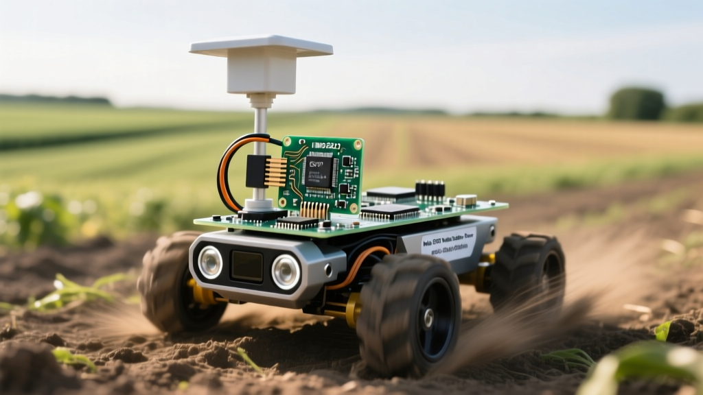
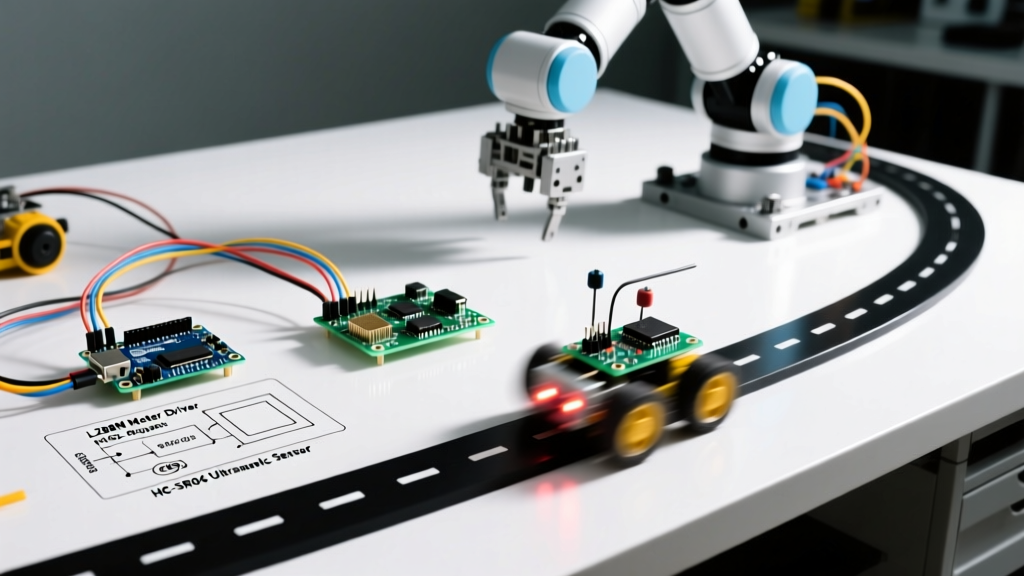
The quintessential robotics rite of passage. However, most beginners fail by using the outdated L298N motor driver, which suffers from a massive 2V voltage drop and poor thermal efficiency. Instead, we will architect this build around modern MOSFET-based drivers and proper power distribution.
Bill of Materials & Cost Breakdown
- Chassis: 2WD Acrylic Kit with TT Motors (~$12.00)
- Motor Driver: TB6612FNG Dual Motor Driver (~$5.50)
- Sensor: HC-SR04 Ultrasonic Sensor on a 180-degree SG90 Servo (~$4.00)
- Power: 2x 18650 Li-ion cells in series (7.4V nominal) in a dual holder (~$8.00)
- Wiring: 22 AWG silicone wire for logic, 18 AWG for main power bus (~$6.00)
Wiring & Edge Cases
The TB6612FNG utilizes MOSFETs instead of BJTs, meaning it drops only about 0.5V. When feeding a 7.4V Li-ion pack into the VMOT pin, your motors will actually see ~6.9V, compared to the dismal 5.4V they would receive from an L298N. Connect the PWMA and PWMB pins to Arduino pins 5 and 6 (which support hardware PWM) to allow for variable speed control, rather than just full-stop or full-speed.
When routing your Power Distribution Board (PDB), keep the high-current 18 AWG motor loops as short as possible to minimize inductive voltage spikes. Always solder a 1000µF electrolytic capacitor directly across the main battery terminals to absorb back-EMF generated when the TT motors abruptly change direction.
Pro Tip: Never power the HC-SR04 VCC pin directly from the Arduino's 5V rail if you are also running a servo. The combined current spike during a ping-and-sweep will cause a brownout, resetting your microcontroller mid-navigation. Use a dedicated 5V step-down buck converter for the sensor and servo rail.
Project 2: 4-DOF Robotic Arm with Power Budgeting
Moving from wheeled locomotion to articulated limbs introduces severe power management challenges. A standard 4-DOF (Degree of Freedom) acrylic arm kit uses four SG90 or MG90S micro servos. This is where 90% of beginner builds fail due to inadequate power budgeting and ignored mechanical tolerances.
The Power Budget Failure Mode
An MG90S metal-gear servo has a stall current of roughly 650mA. If all four servos stall simultaneously (e.g., the arm hits a physical limit or attempts to lift a payload exceeding its 1.8kg-cm torque rating), the total current draw spikes to 2.6 Amps. The Arduino's onboard 5V linear regulator is rated for a maximum of 500mA (and practically much less when powered via the barrel jack due to thermal throttling). Attempting to drive servos directly from the Arduino 5V pin will instantly trigger thermal shutdown or permanently fry the voltage regulator.
The Solution: External UBEC
You must use a UBEC (Universal Battery Eliminator Circuit). A 5V/3A UBEC costs about $6.00 and steps down your 7.4V battery pack to a clean, high-current 5V rail. Wire the UBEC's 5V output directly to the servo power rail on a sensor shield, and ensure the ground (GND) of the UBEC, the battery, and the Arduino are all tied together. Without a common ground, the PWM signals from the Arduino will be unreadable by the servos, resulting in violent jittering and potential gear stripping.
Mechanical Assembly & Backlash
When assembling the acrylic links, do not overtighten the M3 screws. Overtightening causes the acrylic to warp, introducing binding friction that the micro servos cannot overcome. Use nylon locknuts and leave a 0.5mm gap to allow for free rotation, minimizing the baseline current draw of the arm.
Project 3: IR Line-Follower with PID Control
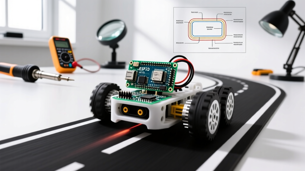
Basic line followers use "bang-bang" control: if the left sensor sees black, turn left; if the right sees black, turn right. This results in a jerky, oscillating motion that is too slow for competitive robotics. To elevate this Arduino beginner project idea into a high-performance machine, you must implement a PID (Proportional-Integral-Derivative) controller.
Sensor Array Setup
Use a 5-channel TCRT5000 infrared sensor array. Mount the sensors exactly 15mm above the track surface using 3D-printed standoffs or brass spacers. Any higher, and ambient IR light from room fixtures will cause false positives; any lower, and the sensor housing will physically scrape the track during high-speed cornering.
Implementing the PID Loop
- Proportional (P): Calculate the error (distance from the center of the line based on the weighted average of the 5 sensors). Multiply by Kp to determine the base steering correction.
- Integral (I): Accumulate the error over time. This helps the robot correct persistent slight drifts caused by uneven motor friction, but keep Ki very low (or zero initially) to prevent overshooting.
- Derivative (D): Calculate the rate of change of the error. This acts as a damper, smoothing out the steering when the robot aggressively crosses the line, preventing the "wagging" effect seen in pure P-controllers.
For a standard 20cm line-following track, starting tuning values are typically Kp = 25, Ki = 0.0, and Kd = 15. Use the Arduino PID Library to handle the math, feeding the output directly into your motor driver's differential steering logic. To tune efficiently, implement a serial plotting function that outputs the real-time Error, P-term, and D-term to the Arduino IDE Serial Plotter, allowing you to visually identify oscillation and adjust gains on the fly.
Troubleshooting Common Robotics Build Failures
Even with perfect code, hardware anomalies will plague your early builds. Use this diagnostic matrix to resolve the most common issues encountered in beginner robotics.
| Symptom | Root Cause | Actionable Fix |
|---|---|---|
| Arduino randomly resets mid-run | Voltage brownout from motor/servo back-EMF or current spikes pulling the logic rail below 4.5V. | Add a 1000µF electrolytic capacitor across the main battery terminals and use separate BECs for logic and motors. |
| TT Motors hum but don't turn | Stall torque exceeded; standard TT motors stall at ~0.8kg-cm, which is easily overwhelmed by heavy chassis or carpet friction. | Reduce payload weight, increase battery voltage, or upgrade to Pololu Micro Metal Gearmotors with a 30:1 gear ratio. |
| Ultrasonic reads 0cm or 400cm randomly | Acoustic echo from nearby walls or missed interrupt timing in the code loop. | Ensure the trig pin is held HIGH for exactly 10µs. Add a mandatory 5ms delay between consecutive pings to prevent ghost echoes. |
| Servos jitter violently when motors spin | Electrical noise from brushed motors coupling into the PWM signal wires. | Reroute PWM signal wires away from motor power cables. If necessary, twist the signal and ground wires together to cancel inductive interference. |
Final Thoughts on Progressing Your Skills
The transition from blinking LEDs to autonomous robotics requires a fundamental shift in how you think about power distribution, mechanical tolerances, and control theory. By selecting modern components like the TB6612FNG and the Uno R4, and by respecting power budgets with external UBECs, your builds will be reliable and robust. Once you master these three foundational Arduino beginner project ideas, the next logical step is integrating an ESP32-CAM for basic computer vision or swapping the ultrasonic sensor for a 2D LiDAR module like the Slamtec RPLIDAR A1 for true SLAM (Simultaneous Localization and Mapping) navigation. Robotics is an iterative discipline; document your failures, refine your power delivery, and let the hardware guide your code.