
Architecting a High-Payload Robot Arm with Arduino
Building a reliable robot arm with Arduino is a cornerstone project in robotics, yet most online tutorials fail at the critical intersection of power delivery and mechanical tolerances. A standard Arduino Uno powering three micro-servos via its onboard 5V regulator is a recipe for brownouts and fried silicon. To build a functional 6-Degree-of-Freedom (DOF) manipulator capable of lifting a 500g payload at a 40cm reach, we must approach the build from an industrial engineering perspective.
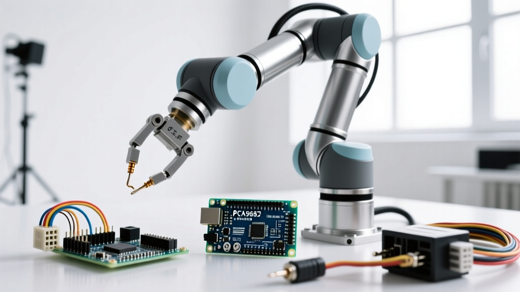
This guide details the complete integration of an Arduino Mega 2560, a PCA9685 I2C PWM driver, and high-torque digital servos. We will cover exact torque mathematics, I2C bus stabilization, and the mechanical edge cases that cause joint slop in DIY robotic arms.
Bill of Materials (BOM) & Component Selection
Component selection dictates the arm's payload capacity and lifespan. We are utilizing a hybrid servo configuration: high-torque digital servos for the base and shoulder (which bear the highest static loads), and standard metal-gear servos for the wrist.
| Component | Model / Specification | Qty | Est. Price (2026) | Engineering Rationale |
|---|---|---|---|---|
| Microcontroller | Arduino Mega 2560 R3 | 1 | $28.00 | Requires multiple hardware serial ports for telemetry and extensive SRAM for kinematic arrays. |
| Servo Driver | Adafruit 16-Channel PCA9685 | 1 | $14.50 | Offloads PWM generation from the MCU via I2C; prevents timer conflicts. |
| Base/Shoulder Servos | DS3218 270° (20kg/cm) | 4 | $68.00 | Digital feedback loop maintains position under heavy static cantilever loads. |
| Elbow/Wrist Servos | MG996R 180° (13kg/cm) | 2 | $18.00 | Cost-effective metal gears for lower-torque distal joints. |
| Power Supply | Mean Well LRS-100-5 (5V 20A) | 1 | $26.00 | Enclosed switching PSU; handles 100W peak transient loads safely. |
| Chassis Material | 3D Printed PETG or CNC Acrylic | 1 | $35.00 | PLA suffers from thermal creep near servo heat sinks; PETG retains rigidity. |
Power Delivery & Torque Mathematics
The most common failure mode in Arduino robotics builds is inadequate power sizing. Servo stall current is vastly higher than operating current. If your arm encounters a hard stop or attempts to lift a load exceeding its kinematic limits, the servos will stall and draw maximum current simultaneously.
Calculating Peak Transient Current
- DS3218 Stall Current: ~2.5A at 5V (x4 = 10.0A)
- MG996R Stall Current: ~2.0A at 5V (x2 = 4.0A)
- Total Peak Draw: 14.0A
To prevent voltage sag—which manifests as servo jitter and I2C bus lockups—your power supply must provide at least 30% overhead above the calculated peak draw. A 14A peak requires a minimum 18.2A supply. The Mean Well LRS-100-5 provides a continuous 20A (100W), making it the optimal choice. Never attempt to power this array through the Arduino's barrel jack or USB port; the onboard linear regulator will thermally shutdown or catastrophically fail within seconds.
Expert Tip: Install a 2200µF electrolytic capacitor (rated for 10V or higher) directly across the V+ and GND terminal blocks on the PCA9685 board. This acts as a local energy reservoir to smooth out the microsecond current spikes generated by digital servo motors switching direction.
Wiring Matrix & I2C Bus Stabilization
The PCA9685 communicates via I2C. While the Arduino Mega 2560 has dedicated SDA and SCL pins, routing these signals to a high-current motor environment requires careful noise management.
| Arduino Mega Pin | PCA9685 Pin | Wire Gauge / Type | Notes |
|---|---|---|---|
| Pin 20 (SDA) | SDA | 24 AWG Shielded Twisted Pair | Keep I2C traces under 30cm to avoid capacitance issues. |
| Pin 21 (SCL) | SCL | 24 AWG Shielded Twisted Pair | Shield must be grounded at the MCU side only. |
| 5V Pin | VCC | 22 AWG Solid Core | Provides logic power (3.3V/5V) to the PCA9685 IC. |
| GND | GND | 18 AWG Stranded | Ensure common ground between MCU and Mean Well PSU. |
| N/A (External) | V+ | 14 AWG Stranded | Direct from Mean Well 5V terminal. Handles high current. |
If your I2C wires must exceed 20cm, the parasitic capacitance of the cable will degrade the square wave signal, causing the Arduino Wire library to hang. In this scenario, solder 4.7kΩ pull-up resistors between the SDA/SCL lines and the 5V logic rail. For comprehensive wiring diagrams and library installation, refer to the Adafruit PCA9685 Servo Driver Guide.
Mechanical Assembly & Edge Cases
Software cannot fix mechanical slop. When assembling a robot arm with Arduino, the physical tolerances of your chassis and servo horns dictate the repeatability of the end-effector.
1. Servo Centering Before Horn Attachment
Never attach a servo horn while the servo is unpowered. Write a simple sketch that commands the PCA9685 to output a 1500µs pulse (the exact neutral position for standard 90°/180° servos). Attach the horn only when the shaft is locked in this neutral state. This ensures your software's 0-180 degree mapping aligns perfectly with the physical limits of the joint.
2. Fastener Threadlocker
Digital servos like the DS3218 produce high-frequency micro-vibrations as they constantly correct positional errors. Standard M2 and M3 screws will back out within hours of operation. Apply a medium-strength threadlocker (such as Loctite 248) to all brass heat-set inserts and chassis screws. Avoid high-strength (red) threadlocker, as it makes maintenance impossible without stripping the plastic threads.
3. Thermal Creep in 3D Printed Chassis
If you are 3D printing your arm links, do not use PLA. PLA has a glass transition temperature of roughly 60°C. High-torque servos easily reach 50°C-65°C under load. The heat transferred through the metal mounting tabs will cause PLA to soften, resulting in joint misalignment. Use PETG, ABS, or ASA, which maintain structural rigidity up to 95°C.
Software Architecture & PCA9685 Integration
When programming your robot arm with Arduino, bypass the standard Servo.h library. The standard library uses hardware timers that conflict with PWM outputs and serial communication on the Mega. Instead, use the Adafruit_PWMServoDriver library.
Pulse Width Calculation
The PCA9685 operates on a 12-bit resolution (4096 steps). At the standard 50Hz servo frequency (20ms period), each step represents approximately 4.88µs. To command a specific angle, you must map the desired pulse width (typically 500µs to 2500µs) to the 4096-step scale.
According to SparkFun's Servo Motor Control Tutorial, the math translates to:
- Minimum Pulse (0°): 500µs / 4.88µs ≈ 102 steps
- Maximum Pulse (180°): 2500µs / 4.88µs ≈ 512 steps
In your setup function, initialize the driver and set the frequency:
pwm.begin();
pwm.setOscillatorFrequency(27000000);
pwm.setPWMFreq(50);
To move Joint 0 to 90 degrees (midpoint), you would send a value of roughly 307 to the setPWM() function. Always implement software limits in your code to prevent the arm from commanding angles that drive the servos past their physical hard stops, which will cause them to draw stall current continuously and burn out the internal potentiometer.
Kinematics: Moving Beyond Hardcoded Angles
A hardcoded sequence of joint angles is useless for dynamic tasks. To make your Arduino robot arm interact with the real world, you must implement Inverse Kinematics (IK). While Forward Kinematics calculates the end-effector's X, Y, Z position based on known joint angles, Inverse Kinematics solves the reverse: calculating the required joint angles to reach a specific X, Y, Z coordinate in 3D space.
For a 6-DOF arm, analytical IK solutions involve complex trigonometric matrices that can bog down the Arduino Mega's 16MHz AVR processor. For real-time path planning, consider implementing a simplified 4-DOF analytical IK for the base, shoulder, elbow, and wrist pitch, while treating the wrist roll and gripper as independent linear axes. If your IK math requires floating-point heavy lifting, consider upgrading the brain to an ESP32-S3 or a Raspberry Pi Zero 2 W, offloading the low-level PCA9685 PWM commands via UART or SPI to a dedicated microcontroller.
Troubleshooting Common Failure Modes
Even with perfect wiring, robotic arms exhibit specific failure modes. Use this diagnostic matrix to resolve issues quickly.
| Symptom | Probable Cause | Engineering Solution |
|---|---|---|
| High-frequency servo jitter at rest | I2C noise or inadequate ground plane. | Add 4.7k pull-up resistors; ensure star-ground topology back to the PSU. |
| Arm resets when lifting heavy payload | Voltage brownout triggering MCU undervoltage lockout. | Separate the MCU 5V logic supply from the Servo V+ supply using two isolated regulators. |
| Shoulder joint slowly droops under load | Servo potentiometer wear or insufficient static torque. | Upgrade to a harmonic drive actuator or implement a mechanical gas-spring counterbalance. |
| PCA9685 stops responding mid-routine | I2C bus lockup due to EMI from servo motors. | Implement a watchdog timer and an I2C bus recovery routine in the Arduino code. |
Final Calibration Notes
Before mounting your end-effector or gripper, run a full range-of-motion test at 20% speed. Verify that no cables are routed near the gear housings where they could be ingested and severed. By respecting the electrical limits of the PCA9685 and the mechanical realities of high-torque servos, your Arduino robot arm will transition from a fragile desktop toy to a robust, repeatable automation platform.