
Engineering a 6-DOF Stewart Platform: The Pinnacle of Arduino 3D Print Projects
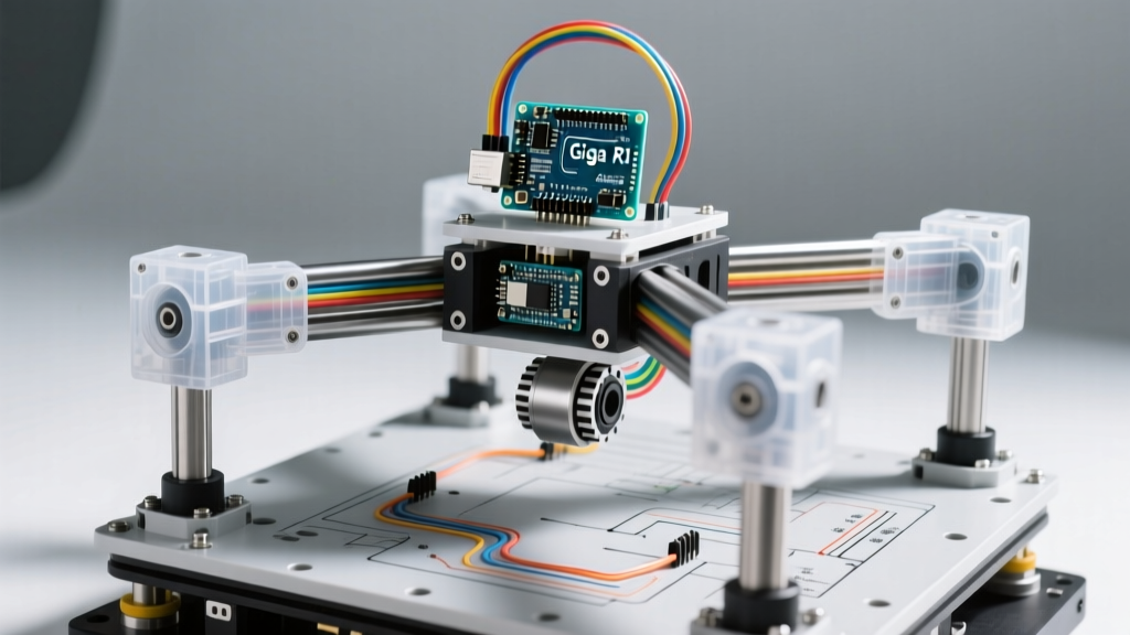
When exploring advanced arduino 3d print projects, most makers stop at static enclosures, basic weather stations, or simple 3-axis robotic arms. To truly test the limits of desktop fabrication and microcontroller computation, we must look toward parallel kinematics. The 6-Degree-of-Freedom (6-DOF) Stewart Platform is a closed-loop parallel manipulator capable of sub-millimeter precision in surge, sway, heave, roll, pitch, and yaw. In 2026, combining high-torque closed-loop steppers with carbon-fiber-reinforced polymers and a dual-core microcontroller transforms this theoretical robotics staple into a highly capable, viable desktop build for camera stabilization, flight simulation, and precision manufacturing.
Bill of Materials & Cost Breakdown
Building a platform capable of handling dynamic loads requires moving beyond standard hobbyist components. The following BOM reflects a professional-grade desktop build optimized for high rigidity and fast computational loop rates.
| Component Category | Specific Model / Specification | Est. Cost (2026) |
|---|---|---|
| Microcontroller | Arduino Giga R1 WiFi (Dual-Core Cortex-M7/M4) | $82.00 |
| Actuators (x6) | BigTreeTech S42B V2.0 Closed-Loop NEMA 17 | $168.00 ($28 ea) |
| Structural Filament | Polymaker PolyMide PA6-CF (Carbon Fiber Nylon) | $95.00 / kg |
| Flexure Joint Filament | NinjaTek NinjaFlex TPU (Shore 85A) | $55.00 / 500g |
| Power Supply | Mean Well LRS-350-24 (24V 15A) | $48.00 |
| Linear Bearings | IGUS DryLin RJMP-01-8 (x6) | $36.00 |
Total Estimated Electronics & Materials Cost: ~$484.00 (excluding hardware and 3D printer depreciation).
Mechanical Design: 3D Printing High-Shear Components
The mechanical integrity of a Stewart Platform relies entirely on the base and top plates resisting severe torsional and shear forces. Standard PLA or PETG will delaminate under dynamic 6-axis acceleration. According to the Prusa Material Guides, engineering-grade filaments require strict environmental controls to print successfully.
Material Selection & Slicer Strategy
- Base & Top Plates (PA6-CF): Carbon-fiber-infused Nylon 6 offers an exceptional strength-to-weight ratio and high thermal deflection resistance. Slicer Settings: 285°C nozzle (hardened steel required), 90°C bed, 0.2mm layer height, 100% infill (gyroid pattern to distribute multi-axis stress evenly).
- Actuator Housings (PETG-CF): For the motor mounts, PolyLite PETG-CF provides sufficient rigidity with easier printability and less moisture absorption than pure Nylon.
- Compliant Flexure Joints (TPU): Instead of traditional spherical rod ends (heim joints) which introduce mechanical backlash and require constant lubrication, advanced builds utilize 3D printed TPU flexure hinges. By printing a compliant mechanism using NinjaFlex (Shore 85A), we achieve zero-backlash rotation. TPU requires a direct-drive extruder and a maximum volumetric flow rate limit of 4.5 mm³/s to prevent heat creep.
Expert Insight: Tolerance Stacking
When designing the press-fit housings for the 8mm bore IGUS bearings, do not rely on standard 0.1mm clearances. PA6-CF exhibits anisotropic shrinkage. Design the bore with a 0.15mm interference fit on the X/Y axes, but print the housing with a 45-degree chamfer at the base to prevent elephant's foot from compressing the bearing outer race, which will cause immediate binding under load.
Electronics: Wiring the Arduino Giga R1 & Closed-Loop Drivers
Standard 8-bit AVR boards like the Arduino Uno are fundamentally incapable of handling the math required for parallel kinematics. The Arduino Giga R1 WiFi Documentation highlights its STM32H747XI dual-core processor (480MHz Cortex-M7), which includes a dedicated hardware Floating Point Unit (FPU). This is non-negotiable for calculating 6x6 Jacobian matrix inversions at a 1kHz control loop frequency.
Power Distribution & Decoupling
Closed-loop steppers draw highly dynamic current spikes during rapid acceleration vectors. A standard 3D printer PSU will trigger over-current protection or cause voltage sags that reset the microcontroller. We mandate the use of a 24V 15A Mean Well LRS-350-24, paired with a 4700µF 35V electrolytic capacitor bank on the main distribution block. This absorbs inductive kickback and stabilizes the voltage rail during simultaneous 6-axis acceleration.
Signal Shielding
The step and direction signals from the Giga R1 to the six BigTreeTech drivers must be routed using shielded twisted-pair (STP) cables. The 24V stepper lines generate massive electromagnetic interference (EMI) that will induce ghost steps in unshielded signal lines, resulting in catastrophic platform collisions. Ground the shield drain wire exclusively at the microcontroller ground plane, leaving the driver end floating to prevent ground loops.
Firmware & Inverse Kinematics (The Math)
Unlike serial kinematics (where X, Y, and Z movements are independent), moving the top plate of a Stewart Platform to a specific Cartesian coordinate requires all six actuators to move simultaneously by different, non-linear amounts. This requires solving inverse kinematics in real-time.
The Computational Pipeline
- Trajectory Planning: The Cortex-M4 core handles trajectory interpolation, generating smooth S-curve acceleration profiles for the target XYZ-Roll-Pitch-Yaw coordinates.
- Kinematic Resolution: The Cortex-M7 core calculates the inverse kinematics. It determines the exact length of each of the 6 virtual struts based on the geometric offset of the universal joints.
- Motor Commutation: The calculated strut lengths are converted into step pulses via hardware timers, ensuring microsecond-level synchronization across all six axes.
Calibration, Singularity Avoidance, and Edge Cases
Hardware assembly is only 40% of the build; the remaining 60% is software calibration and edge-case mitigation.
Auto-Homing with Linear Hall Sensors
Mechanical limit switches suffer from contact bounce and physical degradation. For sub-millimeter repeatability, integrate SS49E linear Hall effect sensors into the base of each actuator. By embedding a small neodymium magnet on the moving carriage, the Arduino can read the analog voltage gradient and home each axis to a repeatable accuracy of ±0.05mm, far exceeding the capability of standard microswitches.
The Singularity Problem
A critical failure mode in parallel kinematics is the "singularity point." This occurs when the vectors of the actuators intersect or align in a way that grants the platform infinite theoretical mechanical advantage in a specific direction. At these points, the required motor torque spikes to infinity, resulting in missed steps, mechanical binding, or shattered 3D printed joints.
Software Mitigation: Your Arduino firmware must include a strict geometric bounding box. Calculate the alpha angles (the angle between the base plate and the actuator strut). If any actuator's alpha angle exceeds 38 degrees or drops below 15 degrees, the firmware must immediately halt the trajectory and trigger a controlled deceleration ramp. Never allow the top and bottom plates to become perfectly parallel at extreme Z-heights without angular offsets.
FAQ: Advanced Troubleshooting
Q: Why are my closed-loop steppers oscillating at a high frequency when holding position?
A: High-frequency oscillation ("hunting") is usually caused by the PID tuning loop on the BigTreeTech drivers being too aggressive for the mechanical compliance of the 3D printed TPU joints. Connect to the driver via USB and reduce the proportional (P) gain by 15%, while slightly increasing the derivative (D) gain to dampen the micro-vibrations.
Q: Can I use an Arduino Mega 2560 instead of the Giga R1?
A: Technically yes, but practically no. The Mega lacks an FPU. Floating-point matrix math will be handled via software emulation, dropping your control loop frequency from 1000Hz down to roughly 40Hz. This will result in severe platform jitter and audible stepping noise. The dual-core architecture of the Giga R1 or a Teensy 4.1 is mandatory for smooth motion.
Q: How do I prevent PA6-CF from warping off the build plate?
A: PA6-CF is notorious for warping. You must use an adhesive specifically designed for Nylon, such as Magigoo PA, applied to a textured PEI sheet. Furthermore, enclose your 3D printer and maintain an ambient chamber temperature of at least 45°C to prevent rapid cooling and inter-layer delamination.