
The Evolution of Arduino and LED Projects
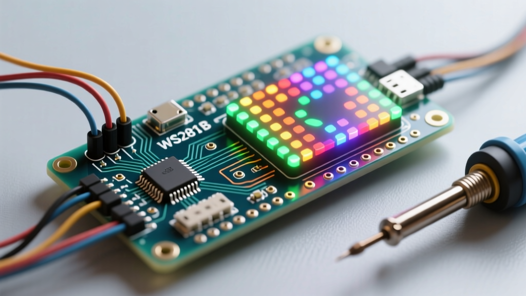
When most makers begin exploring Arduino and LED projects, the journey typically starts with blinking a single 5mm through-hole resistor. However, as your embedded systems expertise grows, so does the ambition of your builds. In 2026, the intersection of digital signal processing (DSP) and high-density addressable lighting has made professional-grade audio visualizers accessible on a DIY budget. This tutorial bypasses the basic tutorials and dives straight into a complex, real-world build: an 8x32 WS2812B FFT (Fast Fourier Transform) Audio Visualizer powered by the Arduino Nano ESP32.
Unlike basic analog microphone modules that suffer from severe noise floors and latency, this build utilizes an I2S MEMS microphone for pristine digital audio capture, paired with hardware-level logic shifting to guarantee signal integrity. Whether you are building a desktop spectrum analyzer or an interactive wall installation, this guide provides the exact engineering specifications required for a flawless deployment.
Bill of Materials & 2026 Cost Analysis
Sourcing reliable components is critical for high-speed data and audio processing. The Arduino Nano ESP32 is selected here for its dual-core 240MHz processing power, native I2S peripherals, and seamless integration with the Arduino IDE and FastLED library.
| Component | Specific Model / Specification | Est. Price (2026) | Engineering Purpose |
|---|---|---|---|
| Microcontroller | Arduino Nano ESP32 (ABX00092) | $27.50 | Dual-core DSP, I2S bus, WiFi/BLE |
| LED Matrix | WS2812B 8x32 Flexible Matrix (256 LEDs) | $18.00 | High-density RGB display surface |
| Audio Capture | INMP441 I2S MEMS Microphone | $4.50 | Digital audio stream, low noise floor |
| Logic Level Shifter | 74AHCT125 Quad Buffer (DIP or SMD) | $1.20 | 3.3V to 5V data line translation |
| Power Supply | Mean Well LRS-50-5 (5V 10A Enclosed) | $24.00 | Stable, low-ripple DC power |
| Passive Components | 1000µF 10V Cap, 330Ω Resistor, Wiring | $3.00 | Transient suppression & ringing prevention |
Total Estimated Build Cost: ~$78.20
Power Architecture & Safety Margins
A common failure mode in advanced Arduino and LED projects is inadequate power budgeting. The WS2812B datasheet specifies a maximum current draw of 60mA per LED (20mA per RGB channel). For 256 LEDs, the theoretical maximum is 15.36 Amps. However, purchasing a 20A power supply is unnecessary and expensive for this specific application.
Engineering Insight: According to the Adafruit NeoPixel UberGuide, typical usage rarely exceeds 30% of the theoretical maximum unless the display is locked at 100% pure white. By implementing a software brightness limiter in FastLED (capping global brightness to 70% and avoiding pure white states), a high-quality 5V 10A (50W) power supply like the Mean Well LRS-50-5 provides more than enough headroom while maintaining a compact form factor.
Mandatory Power Conditioning
- Decoupling Capacitor: Solder a 1000µF electrolytic capacitor directly across the 5V and GND terminals at the power injection point on the LED matrix. This absorbs transient voltage spikes when large banks of LEDs switch on simultaneously.
- Wire Gauge: Use a minimum of 16 AWG silicone wire for the main 5V and GND lines from the PSU to the matrix. Voltage drop across thin wires will cause the far end of the matrix to flicker or shift to brown/yellow hues.
Step 1: I2S Microphone & Logic Shifter Wiring
The INMP441 outputs a digital I2S stream, completely bypassing the noisy analog-to-digital converters (ADC) found on cheaper MAX9814 modules. However, because the Arduino Nano ESP32 operates at 3.3V logic and the WS2812B requires 5V logic for its data line (DIN), we must use the 74AHCT125 to prevent data corruption and the dreaded "random first LED color" bug.
System Pinout Matrix
| Source Component | Source Pin | Destination Component | Destination Pin |
|---|---|---|---|
| INMP441 | VDD | Arduino Nano ESP32 | 3V3 |
| INMP441 | GND | Arduino Nano ESP32 | GND |
| INMP441 | SCK (Serial Clock) | Arduino Nano ESP32 | D5 (GPIO 5) |
| INMP441 | WS (Word Select) | Arduino Nano ESP32 | D6 (GPIO 6) |
| INMP441 | SD (Serial Data) | Arduino Nano ESP32 | D4 (GPIO 4) |
| Arduino Nano ESP32 | D2 (GPIO 2) | 74AHCT125 | 1A (Input) |
| 74AHCT125 | 1Y (Output) | WS2812B Matrix | DIN (via 330Ω Resistor) |
| PSU 5V | 5V DC | 74AHCT125 | VCC |
Critical Wiring Note: Always place a 330Ω resistor on the data line after the 74AHCT125 output and before the WS2812B DIN pin. This resistor prevents high-frequency signal ringing and reflections on the data line, which can cause cascading LED flicker. For a comprehensive pin mapping reference, consult the official Arduino Nano ESP32 Cheat Sheet to ensure you are not conflicting with internal flash SPI pins.
Step 2: FastLED & FFT Firmware Configuration
The core of this project relies on capturing audio buffers via I2S, applying a Fast Fourier Transform (FFT) to decompose the audio into frequency bins, and mapping those bins to the 32 columns of the LED matrix.
Audio Sampling Parameters
To achieve a responsive visualizer without overloading the ESP32's memory, configure your I2S driver and FFT library with the following parameters:
- Sample Rate: 10,240 Hz (Sufficient for capturing up to 5kHz, which covers the majority of musical fundamentals and vocal ranges).
- FFT Window Size: 1024 samples (Provides 512 frequency bins, yielding a frequency resolution of exactly 10 Hz per bin).
- Window Function: Hann Window (Minimizes spectral leakage, ensuring bass frequencies don't artificially bleed into the mid-range visual columns).
Logarithmic Frequency Mapping
Human hearing is logarithmic, not linear. If you map the 512 linear FFT bins directly to your 32 matrix columns, the first 5 columns will represent the bass frequencies, and the remaining 27 columns will represent high frequencies that are rarely active. You must implement a logarithmic mapping array in your C++ code. Group the lower bins (10Hz - 250Hz) into wider visual columns, and compress the higher frequencies (2kHz - 5kHz) into single columns. This creates the fluid, balanced visual response seen in professional spectrum analyzers.
ESP32 FastLED Warning: When using FastLED on ESP32-based boards, the WiFi and Bluetooth radios can cause interrupt conflicts that result in LED flickering. As documented in the FastLED ESP32 Notes, you should either disable WiFi entirely for this standalone build, or use the
FASTLED_ESP32_I2Sdriver workaround to isolate the LED data stream from CPU interrupts.
Step 3: Edge Cases & Hardware Troubleshooting
Even with perfect wiring, DSP-based Arduino and LED projects present unique debugging challenges. Here is how to diagnose the most common failure modes encountered during bench testing.
1. The "First LED is Always Green/Random" Bug
Symptom: The first LED in the chain displays a static, incorrect color, while the rest of the matrix responds correctly to the audio.
Root Cause: The WS2812B protocol requires a data high signal of at least 0.7 x VDD (which is 3.5V for a 5V supply). The Nano ESP32 outputs 3.3V. While some LED batches tolerate 3.3V, the first LED in the chain often misinterprets the voltage threshold, corrupting the first 24 bits of data.
Solution: This is exactly why the 74AHCT125 level shifter is included in the BOM. Ensure the 74AHCT125 VCC is tied to 5V, not 3.3V, to properly shift the logic high to 5.0V.
2. High-Frequency Audio Hum & Visual Noise Floor
Symptom: The bottom row of the matrix constantly flickers with low-level noise, even in a quiet room.
Root Cause: A ground loop between the switching power supply and the microcontroller, or the I2S mic picking up EMI from the LED matrix PWM switching.
Solution: Implement a "Star Ground" topology. Connect the GND of the PSU, the GND of the Nano ESP32, and the GND of the INMP441 to a single, central physical point (like a copper bus bar or a dedicated ground terminal block). Do not daisy-chain the grounds through the breadboard or thin jumper wires.
3. FFT Smearing and Lag
Symptom: The visualizer reacts sluggishly to sharp transients like snare drums or handclaps.
Root Cause: Using a moving average filter that is too aggressive, or an FFT window size that is too large (e.g., 2048 or 4096), which increases the time-domain latency.
Solution: Stick to a 1024-sample FFT window. Instead of a simple moving average for the LED decay (the "falling" effect of the bars), implement an exponential decay algorithm in your loop() function. Multiply the previous column height by 0.85 on every frame rather than subtracting a fixed integer. This creates a natural, gravity-like visual decay that feels incredibly responsive.
Final Assembly & Acoustic Calibration
Once the firmware is flashed and the bench test confirms accurate frequency mapping, mount the 8x32 flexible matrix into a 3D-printed diffuser enclosure. Use a 3mm thick acrylic sheet with a sandblasted finish to blend the individual LEDs into seamless vertical bars of light. Position the INMP441 microphone at the front edge of the enclosure, facing the primary audio source, and seal the rear of the microphone cavity with acoustic foam to prevent phase cancellation from rear-reflected sound waves.
By combining robust power engineering, proper logic level translation, and logarithmic DSP mapping, this build elevates the standard of what is possible with Arduino and LED projects, resulting in a commercial-grade audio visualizer built entirely on your workbench.