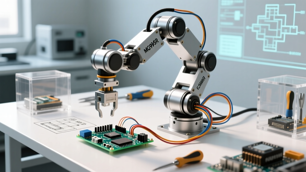

Building a fully functional, 6-Degree of Freedom (6-DOF) Arduino robot arm is a rite of passage for robotics enthusiasts and automation engineers. Unlike simpler 3-DOF or 4-DOF models that merely point an end-effector in a general direction, a 6-DOF arm can achieve any position and orientation within its workspace. This makes it ideal for complex pick-and-place operations, PCB soldering assistance, and 3D printing tasks. However, moving from a toy-like kit to a precision machine requires overcoming significant hurdles in torque management, power distribution, and kinematic programming.
Why 6-DOF and the PCA9685 Advantage
A standard Arduino Uno or Mega has hardware timers that can reliably generate Pulse Width Modulation (PWM) signals for about 12 servos, but doing so directly from the microcontroller's GPIO pins often results in signal jitter. When you are commanding a metal-gear servo to hold a position within a 0.1-degree tolerance, microsecond-level PWM jitter translates into visible mechanical shaking.
The solution is offloading PWM generation to a dedicated I2C controller. The Adafruit 16-Channel 12-bit PWM/Servo Driver (PCA9685) is the industry standard for this application. It communicates via I2C, freeing up your Arduino's processing cycles for inverse kinematics calculations while maintaining rock-solid, hardware-timed PWM signals for your servos.
Bill of Materials (BOM) & 2026 Cost Breakdown
To build an arm capable of lifting a 500g payload at a 400mm reach, you cannot rely on standard plastic micro-servos. Below is the optimized BOM for a heavy-duty desktop build.
| Component | Model / Specification | Est. Cost (2026) | Purpose |
|---|---|---|---|
| Microcontroller | Arduino Mega 2560 (Clone or Genuine) | $18.00 | Brain; handles complex IK math and serial comms |
| Servo Driver | PCA9685 16-Channel PWM Board | $4.50 | Jitter-free hardware PWM generation via I2C |
| Base/Shoulder Servos | 3x MG996R (Metal Gear, 13kg-cm) | $24.00 | High-torque lifting for Joints 1, 2, and 3 |
| Wrist/End-Effector Servos | 3x MG90S (Metal Gear, 2.2kg-cm) | $15.00 | Compact, precise orientation control |
| Power Supply | 5V 10A (50W) Switching PSU (e.g., Mean Well) | $22.00 | Handles simultaneous servo stall currents |
| Chassis | 6-DOF Aluminum Alloy Bracket Kit | $45.00 | Structural integrity under high torque |
| Passives & Wiring | 1000µF Capacitor, 14AWG Silicone Wire | $8.00 | Voltage stabilization and safe current routing |
Mechanical Assembly & Torque Considerations
The most common failure mode in DIY robotics builds is chassis fracture. Acrylic laser-cut kits are cheap and visually appealing, but they are entirely unsuited for the 13 kg-cm stall torque of the MG996R servos used in the base and shoulder joints. Under dynamic load (acceleration and deceleration), the shockwaves will snap acrylic mounting tabs. Always opt for CNC-machined aluminum brackets for the first three joints.
Bearing Support for the Base Joint
Joint 1 (the base rotation) bears the entire weight of the arm plus the payload. Relying solely on the internal potentiometer and plastic bushings of the MG996R to support this axial load will strip the servo gears within hours. You must integrate a thrust bearing or a lazy susan bearing between the base plate and the rotating shoulder mount to offload the axial weight from the servo spline.
Wiring the PCA9685 to the Arduino Mega
The PCA9685 operates at 3.3V logic but is 5V tolerant, making it perfectly compatible with the 5V logic levels of the Arduino Mega. Wiring is straightforward but requires attention to pull-up resistors.
- VCC to Logic: Connect the PCA9685 VCC pin to the Arduino Mega's 5V pin. This powers the I2C logic chip, not the servos.
- GND: Connect the PCA9685 GND to the Arduino GND. Do not skip this. I2C requires a common ground reference.
- SDA/SCL: On the Arduino Mega, connect SDA to Pin 20 and SCL to Pin 21. (Note: This differs from the Uno/Nano, which use A4 and A5).
- Servo Power (V+): Connect your external 5V 10A PSU positive terminal to the green screw terminal block on the PCA9685 (labeled V+).
- PSU Ground: Connect the PSU negative terminal to the GND screw terminal on the PCA9685, and run a secondary ground wire to the Arduino Mega's GND.
Expert Tip: The I2C bus on the Arduino Mega has internal pull-up resistors, but if you are running wires longer than 15cm between the Mega and the PCA9685, add 4.7kΩ external pull-up resistors to the SDA and SCL lines to prevent signal degradation and phantom I2C address errors.
Power Supply Routing: Avoiding Brownouts
Servos do not draw their rated current continuously; they draw it in spikes during acceleration and when stalling against a load. According to Pololu's RC Servo Current Draw Guidelines, a standard high-torque servo like the MG996R can pull up to 2.5A during a stall condition. If your robot arm attempts to move three base servos simultaneously and encounters resistance, you could see a transient current draw of 7.5A.
If your power supply cannot deliver this instantaneous current, the voltage will sag below 4.5V. This causes the Arduino Mega's onboard voltage regulator to drop out, resetting your microcontroller mid-motion, or causes the PCA9685 to lose its I2C synchronization, resulting in violent, uncontrolled servo sweeps.
The Capacitor Buffer Rule
To mitigate transient voltage sag, solder a large electrolytic capacitor directly across the main power input terminals of the PCA9685 board. A 1000µF to 2200µF, 10V or 16V low-ESR capacitor acts as a local energy reservoir, supplying the instantaneous current spikes that the switching PSU's feedback loop might be too slow to catch. Ensure you observe correct polarity; reversing this capacitor will cause it to vent violently.
Inverse Kinematics: Moving Beyond Record-and-Playback
Most beginner tutorials rely on 'record-and-playback' using potentiometers. While fun, this is useless for industrial or automated tasks. To command your Arduino robot arm to move to a specific X, Y, Z coordinate in 3D space, you must implement Inverse Kinematics (IK).
For a 6-DOF arm, the math involves calculating the required angles for all six joints to achieve a target end-effector pose (position + orientation). The most robust method for microcontrollers is the FABRIK (Forward And Backward Reaching Inverse Kinematics) algorithm or the CCD (Cyclic Coordinate Descent) algorithm. Unlike analytical IK using Denavit-Hartenberg (DH) parameters—which requires heavy matrix multiplication and trigonometric functions that can bog down an 8-bit AVR microcontroller—CCD is highly iterative and computationally lightweight.
Implementing CCD on the Arduino Mega
The CCD algorithm works by starting at the end-effector and working backward to the base, rotating each joint one by one to minimize the distance to the target point. The Official Arduino Servo Library Documentation provides the basic framework for writing angles to the hardware, but you will need to map your calculated radians to the PCA9685's 12-bit PWM pulse width values (typically 150 to 600 for a 0 to 180-degree sweep).
When coding the IK solver, always implement joint limits in software. If the IK solver demands a 190-degree rotation from a joint physically limited to 180 degrees, the servo will stall, draw maximum current, and potentially overheat and melt the internal plastic gears.
Troubleshooting Common Jitter and Stall Issues
Even with perfect wiring, environmental and mechanical factors can introduce issues. Use this diagnostic framework to isolate problems:
- High-Frequency Jitter (Vibrating): Usually caused by mechanical backlash in the gear train or a noisy power supply. Ensure your 5V PSU is a high-quality switching supply with low ripple (under 50mV). Cheap, unbranded wall adapters often introduce 100/120Hz AC ripple that translates directly into servo vibration.
- Low-Frequency Wandering (Drifting over time): This is almost always a thermal issue with the servo's internal potentiometer. As the MG996R heats up, the resistance of the carbon track changes, causing the internal feedback loop to miscalculate the position. Add passive heatsinks to the servo casings or implement a software 'sleep' routine that cuts PWM signals when the arm is stationary.
- Random I2C Lockups: If the arm freezes and requires a hard reset, your I2C bus is crashing. This happens when servo EMI (Electromagnetic Interference) couples into the SDA/SCL lines. Route your I2C wires away from the high-current servo power cables, and use shielded twisted-pair cable for the I2C connection.
Final Calibration and Workspace Mapping
Before running your IK code, you must map the physical zero-positions of your servos. Never attach the servo horns while the servo is powered and at an unknown angle. Use the PCA9685 library to command all channels to exactly 90 degrees (a pulse width of roughly 375 on the 12-bit scale). Only then should you mechanically attach the horns, ensuring the arm is in a perfect, straight-up 'home' position. This guarantees that your software coordinate system perfectly aligns with the physical reality of the aluminum chassis, preventing catastrophic collisions when the arm initializes.