
Architecting Reliable IoT Connected Devices
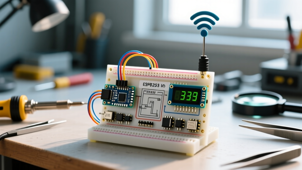
When enthusiasts transition from basic breadboard prototypes to deploying actual IoT connected devices, the complexity of DIY Arduino projects scales exponentially. Building a reliable environmental telemetry node requires more than just copying a sketch; it demands an understanding of power budgets, protocol overhead, and hardware edge cases. In this guide, we engineer a low-power, MQTT-based environmental sensor node using the ESP8266 and the Bosch BME280, specifically addressing the failure modes that plague most amateur IoT builds in 2026.
Hardware Selection: Microcontroller and Sensor Matrix
Choosing the right silicon is the first critical decision. While the classic Arduino Uno is fantastic for learning, it lacks native networking. For modern IoT deployments, the Espressif ecosystem dominates due to its cost-to-performance ratio and deep community support.
| Microcontroller | Architecture | Deep Sleep Current | Avg. 2026 Price | Best Use Case |
|---|---|---|---|---|
| NodeMCU V3 (ESP8266) | Tensilica L106 32-bit | ~20 µA | $4.50 - $5.50 | Low-cost, single-sensor telemetry |
| ESP32-DevKitC V4 | Xtensa Dual-Core 32-bit | ~10 µA | $6.50 - $8.00 | Multi-sensor, BLE + Wi-Fi gateways |
| Arduino Nano 33 IoT | ARM Cortex-M0+ (SAMD21) | ~45 µA (Wi-Fi off) | $18.00 - $21.00 | ECC608 Crypto, enterprise IoT |
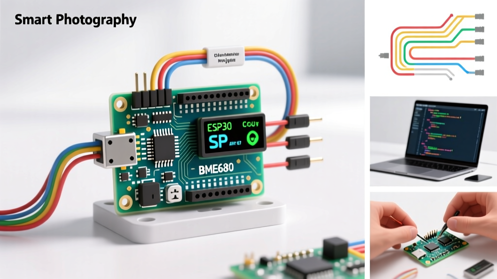
For this build, we are utilizing the NodeMCU V3 (ESP8266) paired with the Bosch BME280 environmental sensor. The BME280 is vastly superior to the aging DHT22, offering an I2C interface, ±3% relative humidity accuracy, and a 1-second measurement time compared to the DHT22's sluggish 2-second blocking delay. According to Bosch Sensortec's official datasheet, the BME280 draws a mere 3.6 µA at a 1Hz sampling rate, making it ideal for battery-operated nodes.
Wiring and the I2C Pull-Up Resistor Trap
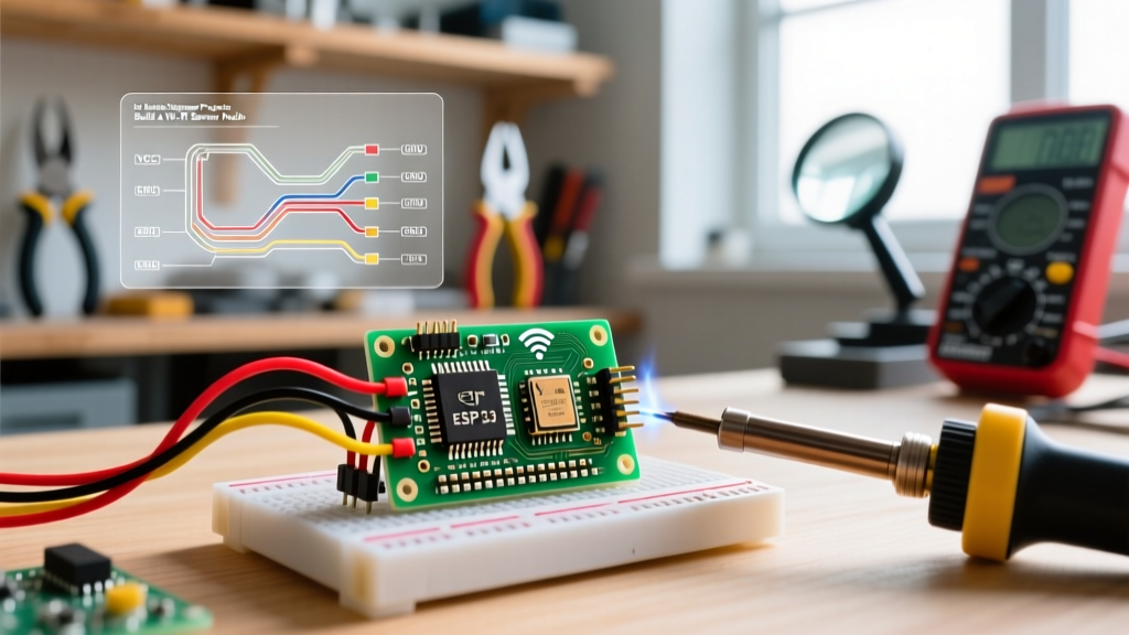
The most common point of failure in beginner DIY Arduino projects involving I2C sensors is ignoring bus capacitance and pull-up requirements. The ESP8266 operates at 3.3V logic. The BME280 must be powered via the 3.3V pin, never the VIN/5V pin, or you risk frying the sensor's internal CMOS circuitry.
Pinout Configuration (NodeMCU V3 to BME280)
- VCC: 3.3V (NodeMCU 3V3 pin)
- GND: Common Ground
- SCL: D1 (GPIO5)
- SDA: D2 (GPIO4)
Expert Troubleshooting Note: Many sub-$2 clone BME280 breakout boards omit the 10kΩ I2C pull-up resistors to save manufacturing costs. If your I2C scanner finds the address (0x76 or 0x77) but data reads return NaN or freeze after 10 minutes, your bus is floating. Solder 4.7kΩ pull-up resistors between the SDA/SCL lines and the 3.3V rail to stabilize the signal edges and eliminate ghost readings.
MQTT Protocol: Designing the Telemetry Payload
HTTP REST APIs are inefficient for IoT telemetry due to heavy header overhead and the requirement for constant polling or complex webhook setups. MQTT (Message Queuing Telemetry Transport) is the undisputed standard for lightweight pub/sub messaging. As outlined in the OASIS MQTT v5.0 specification, the protocol minimizes network bandwidth and ensures reliable delivery via QoS (Quality of Service) levels.
JSON Payload Structure
Instead of publishing raw comma-separated strings, structure your data in JSON. This allows backend databases like InfluxDB or TimescaleDB to parse the payload natively via Telegraf or Node-RED without custom regex parsers.
{
  "node_id": "esp8266_barn_01",
  "timestamp": 1709234567,
  "metrics": {
    "temp_c": 22.45,
    "humidity_pct": 45.2,
    "pressure_hpa": 1013.25,
    "battery_v": 3.82
  },
  "status": {
    "wifi_rssi": -64,
    "uptime_s": 14
  }
}
To implement this, use the PubSubClient library alongside ArduinoJson. Set your MQTT Keep-Alive interval to 60 seconds. If the broker (e.g., Mosquitto or HiveMQ) does not receive a PINGREQ within 1.5x this interval, it will drop the connection and flag the node as offline, triggering your monitoring alerts.
Power Optimization: Calculating Deep Sleep Budgets
An IoT connected device tethered to a USB cable isn't truly wireless. To run off a standard 18650 Li-Ion battery (3.7V, 3000mAh), we must leverage the ESP8266's Deep Sleep mode. In this state, the CPU and Wi-Fi radio are shut down, and only the RTC (Real-Time Clock) remains active to trigger a wake-up.
Battery Life Calculation Matrix
| State | Current Draw | Duration per Cycle | Energy per Cycle |
|---|---|---|---|
| Boot & Wi-Fi Connect | ~80 mA | 3.5 seconds | 0.077 mAh |
| Sensor Read & MQTT TX | ~120 mA | 1.5 seconds | 0.050 mAh |
| Deep Sleep | 0.02 mA (20 µA) | 900 seconds (15 min) | 0.005 mAh |
Total Cycle Cost: ~0.132 mAh every 15 minutes.
Cycles per day: 96.
Daily Consumption: ~12.67 mAh.
Theoretical Battery Life: 3000 mAh / 12.67 mAh = 236 days (assuming 85% voltage regulator efficiency and battery discharge cutoff at 3.0V).
To enable deep sleep in your code, you must physically wire GPIO16 (D0) to the RST pin. Without this hardware bridge, the ESP.deepSleep(900e6) command will put the chip to sleep, but it will never wake up, requiring a manual physical reset.
Handling Edge Cases and Network Dropouts
Real-world RF environments are noisy. A microwave oven or a neighboring router changing channels can easily drop your ESP8266's Wi-Fi connection mid-transmission. Robust DIY Arduino projects must account for these failures gracefully.
- Wi-Fi Timeout Failsafe: Never use a blocking
while(WiFi.status() != WL_CONNECTED)loop without a timeout counter. If the router is down, your node will hang, drain the battery at 80mA, and die within 48 hours. Implement a 10-second timeout that forces a deep sleep if connection fails. - MQTT QoS Selection: Use QoS 1 (At least once delivery) for environmental telemetry. QoS 0 risks dropped packets during brief network hiccups, while QoS 2 introduces too much handshake overhead and latency for simple sensor data.
- ADC Battery Monitoring: The ESP8266 ADC pin (A0) accepts a maximum of 1.0V. To measure a 4.2V Li-Ion cell, you must build a voltage divider using a 220kΩ and a 100kΩ resistor. Failing to divide the voltage will permanently damage the internal ADC circuitry.
Frequently Asked Questions
Can I use a BMP280 instead of a BME280?
While the BMP280 shares the same I2C footprint and pinout, it lacks the onboard humidity sensor. If your IoT use case requires dew point calculations or greenhouse monitoring, the missing capacitive humidity element renders the BMP280 insufficient. Always verify the silicon marking; many cheap boards advertise BME280 but ship with BMP280 chips.
Why does my ESP8266 reset when the Wi-Fi router reboots?
This is typically caused by a brownout. When the ESP8266 attempts to reconnect at maximum RF transmit power (up to 170mA peak), a weak 3.3V voltage regulator (like the AMS1117 on cheap NodeMCU clones) will drop voltage below the 2.5V threshold, triggering the hardware watchdog reset. Soldering a 100µF tantalum capacitor across the 3.3V and GND pins near the chip stabilizes the transient current spikes.
Finalizing the Deployment
Building professional-grade IoT connected devices through DIY Arduino projects requires shifting your mindset from "making it work on the desk" to "ensuring it survives in the field." By selecting the right low-power silicon, hardening your I2C bus against capacitance issues, utilizing MQTT for efficient payload delivery, and mathematically validating your deep sleep budgets, you transform a fragile prototype into a resilient, deployment-ready telemetry node.
For further reading on low-power Wi-Fi architectures, consult the Espressif ESP8266 hardware design guidelines to ensure your custom PCB layouts minimize quiescent current draw.