
The Reality of the L298N in Modern Prototyping
The L298N dual full-bridge motor driver has been a staple in robotics and DIY electronics for over a decade. However, as we navigate the hardware landscape of 2026, the L298N motor driver Arduino ecosystem presents unique challenges. Originally designed by STMicroelectronics using bipolar junction transistor (BJT) technology, the L298N is fundamentally an older architecture. While modern MOSFET-based drivers have largely superseded it in commercial products, the L298N remains ubiquitous in educational kits and budget prototyping due to its low entry cost (typically $2.50 to $4.00 per module).
Troubleshooting the L298N requires understanding its internal Darlington pair configuration, its strict logic-level requirements, and its thermal limitations. This guide bypasses generic advice and dives deep into the exact failure modes, multimeter diagnostics, and engineering realities of integrating this chip with modern microcontrollers.
Master Diagnostic Matrix
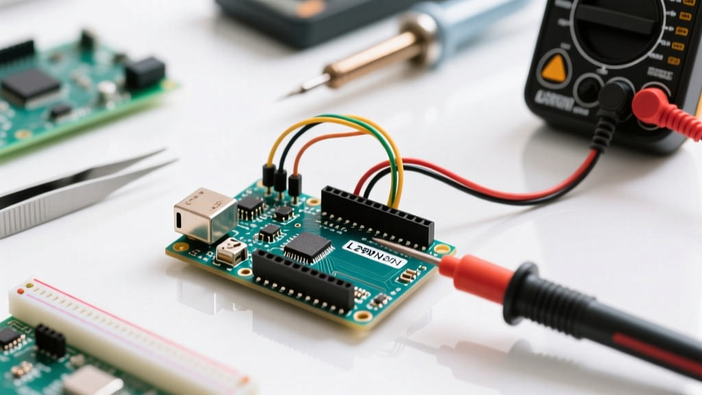
Before desoldering wires or rewriting your sketch, use this diagnostic matrix to isolate the root cause of your hardware failure. Keep a digital multimeter (DMM) handy to verify these states.
| Symptom | Multimeter Reading | Root Cause | Resolution Protocol |
|---|---|---|---|
| Motor runs weakly or hums | V_out is 1.8V - 2.5V lower than V_in | Internal BJT voltage drop (Vce_sat) | Increase V_in to 9V-12V or switch to a MOSFET driver |
| Erratic speed control via PWM | Logic pins read 3.3V during HIGH state | 3.3V MCU logic level mismatch | Implement a logic level shifter or use 5V tolerant MCU |
| Module is too hot to touch | Current draw exceeds 1.2A continuous | Thermal junction limit exceeded | Add forced air cooling or reduce duty cycle |
| Arduino resets on motor start | 5V rail dips below 4.2V transiently | Ground bounce and Back-EMF noise | Isolate grounds, add bulk capacitance (470µF) |
| Onboard 5V regulator fails | 5V pin outputs 0V or >7V | Input voltage exceeded 7805 limits | Remove 5V jumper if V_in > 12V; use external BEC |
Fault 1: The 'Ghost' Voltage Drop (Weak Motor Performance)
The most frequent complaint among beginners is that a 5V DC motor connected to the L298N barely spins when powered by a 5V supply. This is not a defect; it is a fundamental characteristic of the silicon.
The Physics of the Vce(sat) Drop
According to the STMicroelectronics L298N Datasheet, the internal H-bridge relies on Darlington transistor pairs. When current flows through the driver, it must pass through two junctions. This results in a saturation voltage drop (Vce_sat) of typically 1.8V, and up to 2.5V at higher currents (1A to 2A).
Field Note: If you feed 5V into the VCC terminal of the L298N, your motor will only ever receive a maximum of 3.2V under load. Furthermore, counterfeit or low-binned clone chips prevalent in 2026 budget marketplaces often exhibit drops closer to 3.0V, leaving your motor with a useless 2.0V.
The Fix: To drive a standard 5V motor effectively, you must supply at least 7.5V to 8V to the L298N VCC input. The chip will drop ~2V, delivering the required 5.5V to 6V to the motor terminals. If your power budget restricts you to a single-cell 3.7V LiPo battery, the L298N is the wrong component. You must pivot to a low-Vf MOSFET driver like the TB6612FNG or DRV8833.
Fault 2: 3.3V Logic Level Mismatches
With the dominance of 3.3V microcontrollers like the ESP32-S3, Raspberry Pi Pico (RP2040), and Arduino Nano 33 IoT, logic level translation has become a primary point of failure. The L298N was designed in the 5V TTL era.
Decoding the Logic Thresholds
The L298N requires a minimum Logic HIGH input voltage (VIH) of 2.3V to register a '1'. While a 3.3V ESP32 pin technically exceeds this threshold, the noise margin is dangerously thin. When PWM signals are introduced, the rapid switching and parasitic capacitance of the module's optocouplers (if equipped on premium clones) or direct traces can cause the 3.3V signal to degrade, resulting in missed pulses, erratic motor stuttering, or complete failure to engage.
The Fix: Do not rely on marginal 3.3V logic. Use a bidirectional logic level shifter (such as the BSS138-based 4-channel modules available for ~$1.50) to step the ESP32's 3.3V PWM signals up to a clean 5V logic level. Alternatively, if you are designing a custom PCB, integrate a dedicated 3.3V-to-5V gate driver IC before the L298N inputs.
Fault 3: Thermal Shutdown and the 7805 Trap
The standard red L298N module found on Amazon and AliExpress includes an onboard 7805 linear voltage regulator. This component is intended to drop the motor supply voltage down to 5V to power the Arduino. However, this feature is a frequent source of catastrophic failure.
The 12V Jumper Rule
The 7805 regulator has a maximum input voltage rating of 35V, but its thermal dissipation capability is abysmal without a massive heatsink. The power dissipated as heat is calculated as P = (Vin - 5V) * I. If you supply 14V to the motor terminals and draw just 50mA for your Arduino logic, the 7805 must dissipate nearly half a watt of heat. In the enclosed, poorly ventilated space beneath the L298N heatsink, the regulator will enter thermal shutdown, killing power to your microcontroller.
The Fix: If your motor supply voltage exceeds 12V, you must remove the 5V enable jumper cap on the module. Power your Arduino via its own dedicated USB connection or a separate buck converter (like an LM2596 module set to 5V). For a comprehensive look at selecting the right power architecture, refer to the Adafruit Motor Selection Guide, which details modern power delivery topologies.
Fault 4: Arduino Resets and Ground Bounce
A classic symptom of poor peripheral integration is the Arduino spontaneously resetting or freezing the moment the motor changes direction or starts under a heavy mechanical load. This is rarely a software bug; it is an electromagnetic interference (EMI) and ground bounce issue.
Back-EMF and Flyback Diode Limitations
DC motors are inductive loads. When the L298N cuts power or reverses polarity, the collapsing magnetic field generates a massive reverse voltage spike (Back-EMF). The L298N module includes eight 1N4007 flyback diodes to clamp these spikes. However, the 1N4007 is a standard rectifier diode with a slow reverse recovery time (trr of ~30µs). If you are driving the L298N with high-frequency PWM (above 1kHz) to achieve smooth motor control, the 1N4007 diodes cannot react fast enough, allowing voltage spikes to bleed into the shared ground plane.
The Fix:
- Star Grounding: Never daisy-chain your grounds. Wire the battery negative, the L298N GND, and the Arduino GND to a single, common physical point (a star ground) to prevent high-current motor return paths from modulating the Arduino's logic ground.
- Bulk Capacitance: Solder a 470µF to 1000µF electrolytic capacitor directly across the VCC and GND screw terminals on the L298N module. This acts as a local energy reservoir, absorbing transient voltage dips during motor startup.
- Upgrade Diodes: For high-frequency PWM applications, bypass the onboard 1N4007s and solder fast-recovery Schottky diodes (like the 1N5819) across the motor terminals.
Fault 5: Enable Pin (ENA/ENB) PWM Frequency Limits
When using the Arduino Motor Control Documentation as a baseline, many users apply the default `analogWrite()` function to the ENA/ENB pins. On most AVR-based Arduinos (like the Uno R3), this defaults to ~490Hz or 980Hz. While this works, pushing the PWM frequency higher (e.g., 20kHz to eliminate audible motor whine) often causes the L298N to overheat rapidly.
The L298N has relatively slow switching times (turn-on and turn-off times are typically around 2µs). At 20kHz, the period is 50µs. The transistor spends a disproportionate amount of time in the linear (active) region during switching transitions, where it acts as a resistor rather than a closed switch, generating massive amounts of waste heat.
The Fix: Keep your PWM frequency between 500Hz and 1kHz when using the L298N. If your application strictly requires ultrasonic PWM frequencies to eliminate acoustic noise, the L298N is fundamentally incapable of handling it efficiently. You must upgrade to a modern driver.
When to Abandon the L298N: 2026 Upgrade Paths
While troubleshooting can salvage a flawed L298N setup, recognizing when to abandon the chip is a hallmark of engineering maturity. If your project demands high efficiency, battery longevity, or 3.3V native logic, consider these modern alternatives:
- TB6612FNG: A dual-channel MOSFET driver with a voltage drop of only ~0.5V. It handles 1.2A continuous current, natively supports 3.3V logic, and costs roughly $3.00. It is the direct spiritual successor for small robotics.
- DRV8833 / DRV8871: Texas Instruments' brushed DC motor drivers offer built-in overcurrent protection, sleep modes for micro-amp standby currents, and ultra-compact footprints.
- BTS7960: For high-current applications (e.g., 12V windshield wiper motors or e-bike conversions drawing 20A+), the BTS7960 half-bridge modules are the industrial standard, completely eclipsing the L298N's 2A limit.
By understanding the silicon-level limitations of the L298N, you can transition from frustrated guesswork to systematic, data-driven hardware debugging.