
Introduction to Optical Sensors in Microcontrollers
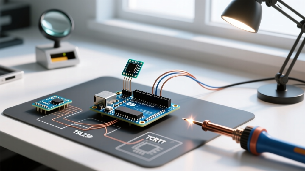
Integrating an optical sensor with an Arduino opens up a massive range of possibilities, from automated greenhouse lighting control to high-speed line-following robots. However, the term 'optical sensor' encompasses vastly different underlying technologies. In this comprehensive 2026 integration tutorial, we will bridge the gap between theory and practical wiring by examining two distinct, industry-standard modules: the TSL2591 High Dynamic Range Digital Light Sensor for precise ambient lux measurement, and the classic TCRT5000 Reflective Optical Sensor for proximity and object detection.
Many beginners struggle with optical sensor Arduino projects because they treat all light sensors identically. A phototransistor behaves entirely differently than a digital CMOS photodiode array. By mastering both I2C digital communication and analog reflective threshold tuning, you will build a robust foundation for any photonics-based microcontroller project.
Sensor Comparison Matrix: Ambient vs. Reflective
Before cutting wires, it is critical to select the right tool for your physical environment. The table below contrasts the two modules we will integrate today.
| Feature | TSL2591 (Ambient) | TCRT5000 (Reflective) |
|---|---|---|
| Primary Function | Measure environmental illuminance (Lux) | Detect object proximity / surface contrast |
| Output Protocol | Digital I2C (Address 0x29) | Analog Voltage / Digital Comparator |
| Optical Spectrum | Broadband + Separate IR Channel | 950nm Infrared (IR) Peak |
| Effective Range | Omnidirectional (up to 88,000 Lux) | Directional (1mm to 25mm gap) |
| Typical 2026 Cost | $6.95 (Adafruit Breakout) | $1.20 (Generic Breakout) |
Hardware BOM and Wiring Prerequisites
To follow this tutorial, ensure you have the following components on your workbench. Pricing reflects standard hobbyist market rates as of early 2026.
- Microcontroller: Arduino Uno R4 Minima or Nano 33 IoT (Note: The R4 operates at 5V logic, necessitating level shifting for the TSL2591).
- Ambient Sensor: Adafruit TSL2591 Breakout (Product ID: 1980).
- Reflective Sensor: TCRT5000 Module with onboard LM393 comparator.
- Logic Level Converter: BSS138 Bidirectional MOSFET module ($1.50) to protect the 3.3V I2C bus.
- Passives: 4.7kΩ pull-up resistors, 100nF decoupling capacitors.
Phase 1: Wiring the TSL2591 I2C Ambient Sensor
The TSL2591 is an advanced ams OSRAM chip that features separate photodiodes for broadband (visible + IR) and IR-only light. This dual-diode architecture allows the internal DSP to mathematically subtract IR interference, yielding a highly accurate human-eye lux response. According to the Adafruit TSL2591 Learning Guide, this sensor can detect light levels from 188 microLux up to 88,000 Lux, making it ideal for outdoor weather stations.
The 5V to 3.3V Logic Level Shifting Mandate
A catastrophic failure mode in optical sensor Arduino projects is frying the I2C bus. The TSL2591 is strictly a 3.3V device. If you are using a 5V Arduino (like the Uno R3 or R4 Minima), connecting the SDA and SCL lines directly will degrade the sensor's internal ESD diodes over time, eventually locking the I2C bus. You must route the I2C lines through a BSS138 bidirectional logic level converter.
Step-by-Step I2C Connections
- Connect the Arduino 5V pin to the HV (High Voltage) pad on the BSS138.
- Connect the Arduino 3.3V pin to the LV (Low Voltage) pad on the BSS138.
- Route Arduino GND to both HV-GND and LV-GND on the level shifter.
- Connect Arduino SDA/SCL to the HV-side channels.
- Connect the TSL2591 SDA/SCL to the LV-side channels.
- Critical Step: Ensure 4.7kΩ pull-up resistors are present on the 3.3V LV-side I2C lines. Most Adafruit breakouts include these, but if you are using raw modules, omitting them will cause the
Wire.hlibrary to hang indefinitely.
Phase 2: Integrating the TCRT5000 Reflective Sensor
While the TSL2591 looks at the sky, the TCRT5000 looks at the ground. This module pairs a 950nm Gallium Arsenide (GaAs) IR LED with an NPN silicon phototransistor. As detailed in the Vishay TCRT5000 Datasheet and Specs, the 950nm wavelength is invisible to the human eye but highly reflective off white surfaces and heavily absorbed by black materials.
Understanding the LM393 Comparator Breakout
Bare TCRT5000 components output a raw analog current. However, the ubiquitous blue breakout boards include an LM393 dual voltage comparator and a 10kΩ trimpot. This gives you two outputs:
- AO (Analog Out): A raw voltage ranging from 0V (high reflection/white surface) to 5V (low reflection/black surface or out of range).
- DO (Digital Out): A clean 5V/0V logic signal that flips when the analog voltage crosses the threshold set by the blue trimpot.
Tuning the Hysteresis Threshold
Do not rely on the factory trimpot setting. To calibrate the DO pin for line-tracking:
- Place the sensor exactly 10mm above your target 'dark' surface.
- Connect a multimeter to the AO pin.
- Using a small Phillips screwdriver, turn the trimpot until the DO pin LED just barely turns off.
- Move the sensor over your 'light' surface. The DO LED should snap on instantly. This mechanical tuning creates hardware-level hysteresis, saving your Arduino CPU from executing software debouncing routines.
Arduino C++ Implementation Strategy
When writing firmware for optical sensors, blocking code is the enemy of real-time control. According to the official Arduino Wire (I2C) Documentation, I2C transactions can take several milliseconds, especially when configuring the TSL2591's integration time registers.
Non-Blocking Polling Architecture
Never place optical sensor reads inside a simple delay() loop. Instead, use a millis() based state machine. Set the TSL2591 integration time to 100ms for general indoor robotics, or 600ms for ultra-low-light astronomy enclosures.
Pro-Tip: If your TCRT5000 analog readings are jittery, do not just average them in software. Solder a 100nF ceramic capacitor directly across the VCC and GND pins on the sensor breakout. This hardware low-pass filter eliminates high-frequency noise from switching voltage regulators before the ADC ever samples it.
Critical Failure Modes and Edge Cases
Even with perfect wiring, environmental physics can derail your project. Here is how to troubleshoot the most common optical sensor anomalies:
- Solar IR Saturation (TCRT5000): Sunlight contains massive amounts of 950nm IR radiation. If you deploy a line-following robot outdoors, the solar IR will saturate the phototransistor, causing the sensor to read 'white' even when hovering over black asphalt. Solution: 3D print a physical shroud around the sensor tip to block ambient angles, or upgrade to a modulated IR sensor like the TSSP4038.
- 50/60Hz Mains Flicker (TSL2591): Indoor LED and fluorescent lighting flickers at 100Hz or 120Hz. If your TSL2591 integration time is not a multiple of the AC cycle (e.g., 100ms or 200ms), your lux readings will oscillate wildly. Solution: Lock the integration time to exactly 100ms or 600ms to mathematically average out the AC waveform ripple.
- I2C Address Collisions: The TSL2591 is hardcoded to I2C address
0x29. If your project requires multiple ambient light sensors for spatial mapping, you cannot simply wire them to the same bus. Solution: Use an I2C multiplexer like the TCA9548A to route the bus to isolated channels.
Summary
Mastering optical sensor Arduino integration requires respecting the physical limitations of light. By utilizing the TSL2591 for mathematically pure lux data and the TCRT5000 for rapid, localized contrast detection, you equip your microcontroller with a robust visual cortex. Always respect 3.3V logic boundaries, tune your analog thresholds mechanically, and filter your power rails to ensure pristine data acquisition.