
Introduction to Arduino Water Leak Detection
Water leaks in residential and commercial properties cause over $13 billion in insurance claims annually. Building a custom early-warning system using an Arduino water sensor is a highly effective, low-cost DIY project. Whether you are monitoring a basement sump pump, an aquarium overflow, or a smart home water heater, interfacing a liquid detection module with a microcontroller requires understanding both the hardware limitations and software filtering techniques.
In this guide, we will move beyond basic "hello world" tutorials. We will cover the critical failure modes of resistive sensors, how to implement a switched-power circuit to prevent electrolysis, and how to write noise-resistant C++ code using a moving average filter to ensure your leak detection system is robust enough for 24/7 deployment.
Hardware Selection: Resistive vs. Capacitive Modules
When makers search for an Arduino water sensor, they typically encounter two primary module types on the market. Understanding the difference is crucial for long-term reliability in damp environments.
| Feature | FC-28 Resistive Module | Capacitive v1.2 / v2.0 |
|---|---|---|
| Sensing Method | Electrical Conductivity | Dielectric Permittivity |
| Average Cost (2026) | $1.20 - $1.80 | $3.50 - $5.00 |
| Corrosion Risk | High (Electrolysis) | None (Coated/Isolated) |
| Output Type | Analog (A0) & Digital (D0) | Analog (A0) Only |
| Onboard IC | LM393 Comparator | 555 Timer / Custom ASIC |
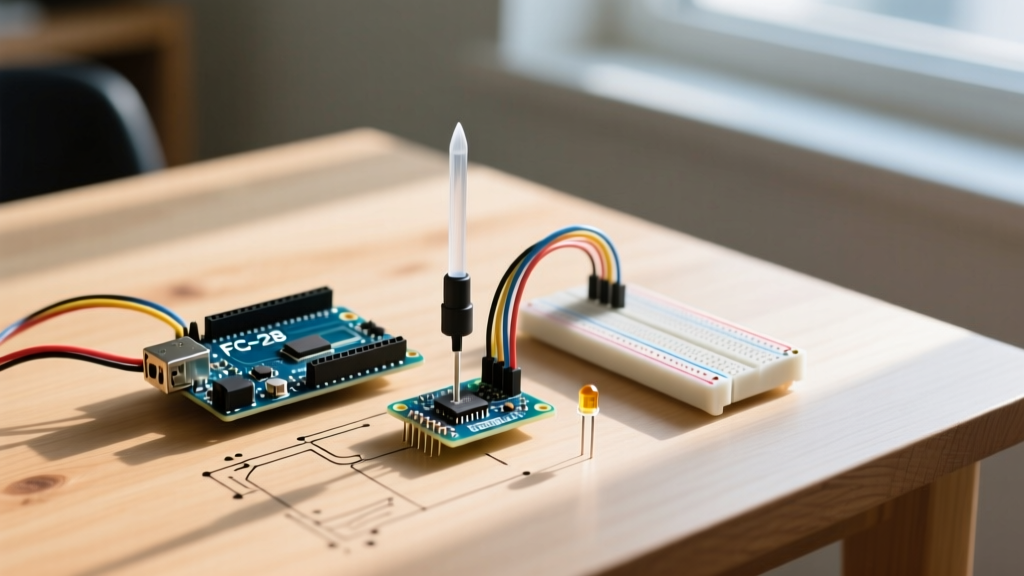
The FC-28 is the most common "rain drop" or water level sensor. It features exposed nickel or copper traces that act as a variable resistor. When water bridges the gap between the traces, resistance drops. The module includes an LM393 comparator chip and a potentiometer to provide a digital HIGH/LOW output on the D0 pin when a specific threshold is crossed.
Conversely, capacitive sensors measure changes in dielectric permittivity through a conformal coating. While they cost roughly three times as much, they are entirely immune to galvanic corrosion, making them the superior choice for permanent, submerged installations.
The Electrolysis Problem (And How to Fix It)
The number one reason beginners abandon the FC-28 Arduino water sensor is rapid corrosion. If you wire the sensor's VCC directly to the Arduino's 5V rail and leave it powered continuously, the DC current passing through the water will cause electrolysis. The exposed metal traces will oxidize and dissolve into the water within 48 to 72 hours, rendering the sensor useless.
Pro-Tip: The Switched Power Method
To extend the lifespan of a resistive sensor from a few days to several years, never leave it continuously powered. Instead, connect the sensor's VCC pin to a digital GPIO pin on the Arduino. Set the pin HIGH only for the 10 milliseconds required to take a reading, then immediately set it LOW. This completely halts the electrolysis process between reads.
Wiring the Arduino Water Sensor
To implement the switched-power method and read the analog signal, you will need a few jumper wires and optionally a ceramic capacitor for noise filtering. According to standard voltage divider principles, the module's internal 10k pull-up resistor and the water's variable resistance create a voltage that the Arduino's ADC can read.
Pinout Connections
- Sensor VCC → Arduino Digital Pin 7 (Switched Power)
- Sensor GND → Arduino GND
- Sensor A0 → Arduino Analog Pin A0
- 100nF Ceramic Capacitor → Bridge between A0 and GND (Optional but highly recommended to filter EMI from nearby AC lines or sump pump motors).
Note: The D0 (Digital Output) pin is left unconnected in this tutorial, as reading the raw analog data via A0 allows for much more granular leak detection and software-based thresholding.
Arduino C++ Code with Moving Average Filter
Raw analog readings from water sensors are notoriously noisy. Water turbulence, mineral deposits, and electromagnetic interference can cause the ADC values to spike wildly. According to the official Arduino analogRead() documentation, the ADC takes about 100 microseconds to sample, but environmental noise requires software smoothing. We will implement a moving average filter, a technique detailed in the Arduino Smoothing Tutorial, to stabilize the output.
const int sensorPowerPin = 7;
const int sensorReadPin = A0;
const int numReadings = 10;

int readings[numReadings];
int readIndex = 0;
int total = 0;
int average = 0;

void setup() {
  Serial.begin(9600);

  // Initialize the power pin as an output and keep it LOW
  pinMode(sensorPowerPin, OUTPUT);
  digitalWrite(sensorPowerPin, LOW);

  // Initialize the readings array
  for (int i = 0; i < numReadings; i++) {
    readings[i] = 0;
  }
}

void loop() {
  // 1. Power the sensor ON
  digitalWrite(sensorPowerPin, HIGH);

  // 2. Wait for the ADC and capacitor to stabilize
  delay(15);

  // 3. Take reading and update the moving average
  total = total - readings[readIndex];
  readings[readIndex] = analogRead(sensorReadPin);
  total = total + readings[readIndex];
  readIndex = readIndex + 1;

  if (readIndex >= numReadings) {
    readIndex = 0;
  }

  average = total / numReadings;

  // 4. Power the sensor OFF to prevent electrolysis
  digitalWrite(sensorPowerPin, LOW);

  // 5. Map the inverted values to a 0-100% scale
  // Dry = 1023 (High Resistance), Wet = 0 (Low Resistance)
  int waterLevel = map(average, 1023, 0, 0, 100);
  waterLevel = constrain(waterLevel, 0, 100);

  Serial.print("Stabilized Water Level: ");
  Serial.print(waterLevel);
  Serial.println("%");

  // Trigger alert if leak detected
  if (waterLevel > 25) {
    Serial.println("ALERT: Water leak detected!");
  }

  // Wait 2 seconds before the next read cycle
  delay(2000);
}
Calibration and Physical Placement
Writing the code is only half the battle. Physical placement dictates the success of your Arduino water sensor project.
- The "Low-Point" Rule: Always place the sensor at the absolute lowest point of the area you are monitoring. Water follows gravity; a sensor mounted half an inch too high will miss a slow, seeping leak until it becomes a flood.
- Angling the Board: Do not mount the FC-28 module flat against a surface. Mount it at a 45-degree angle using a hot-glue gun or a 3D-printed bracket. This prevents water from pooling on the LM393 comparator chip and the potentiometer, which will short out the module's logic side.
- Mineral Calibration: Pure distilled water is actually a poor conductor. Tap water and groundwater contain dissolved minerals (calcium, magnesium, sodium) that drastically lower resistance. If you are testing your sensor in a cup of distilled water, you may get false "dry" readings. Always calibrate using the actual water source you expect to detect.
Troubleshooting FAQ
Why is my sensor reading 1023 when it is completely submerged?
This usually indicates a broken trace or severe corrosion. If the nickel plating on the FC-28 has oxidized and flaked off, the circuit is open, resulting in maximum resistance (1023). Inspect the probes under a magnifying glass. If they appear black or pitted, the sensor must be replaced. This is why the switched-power method outlined above is mandatory for long-term use.
My readings fluctuate between 400 and 800 rapidly. What is wrong?
You are experiencing electromagnetic interference (EMI) or a floating ground. Ensure your Arduino and the sensor share a common, solid ground connection. If the sensor is located near a sump pump motor or an AC mains wire, the 100nF ceramic capacitor mentioned in the wiring section is mandatory to act as a low-pass filter, shunting high-frequency noise to ground before it reaches the A0 pin.
Can I use this sensor to measure the exact volume of water in a tank?
No. The FC-28 Arduino water sensor is a presence and relative level detector, not a volumetric depth gauge. The resistance changes non-linearly based on water conductivity, temperature, and probe surface area. For precise volumetric tank monitoring, you should upgrade to an ultrasonic distance sensor (like the JSN-SR04T) or a hydrostatic pressure transducer.