
Mastering the pH Sensor Arduino Integration for Precision Hydroponics
Integrating a reliable pH sensor Arduino setup is the cornerstone of any automated hydroponic system, aquarium monitor, or water quality testing rig. While early generations of analog pH probes suffered from severe electrical noise and ground loop issues, the modern DFRobot Gravity: Analog pH Sensor / Meter Kit V2 (SKU: SEN0161) has largely solved these problems with onboard voltage regulation and signal isolation. Priced at approximately $59.99 in 2026, it remains the gold standard for hobbyist and prosumer microcontroller projects.
This comprehensive wiring and code guide will walk you through the exact hardware connections, C++ sampling algorithms, two-point calibration protocols, and the critical edge cases that cause 90% of failed pH deployments.
Hardware Breakdown and Specifications
Before wiring, it is crucial to understand the electrical characteristics of the SEN0161 kit. The kit includes the V2 signal conversion board and the E-201-C composite glass electrode.
| Parameter | Specification | Engineering Notes |
|---|---|---|
| Operating Voltage | 3.3V - 5.5V DC | Compatible with both 5V Arduino Uno and 3.3V ESP32 logic levels. |
| Analog Output Range | 0V - 3.3V | Do not feed 5V into the analog out; the board regulates it down to 3.3V max. |
| pH Measurement Range | 0 - 14.0 pH | Optimal accuracy between 2.0 and 12.0 pH. |
| Response Time | ≤ 1 minute (95%) | Highly dependent on solution temperature and probe hydration. |
| Probe Connector | BNC | Standardized; allows swapping with specialized lab-grade probes later. |
For authoritative context on why precise pH matters, the US EPA Secondary Drinking Water Standards recommend a pH range of 6.5 to 8.5 for municipal systems to prevent heavy metal leaching and pipe corrosion. In hydroponics, keeping the root zone between 5.5 and 6.5 is equally critical for nutrient uptake.
Step-by-Step Wiring Protocol
The physical wiring is straightforward, but where you place the wires dictates your signal-to-noise ratio.
Pinout Connections
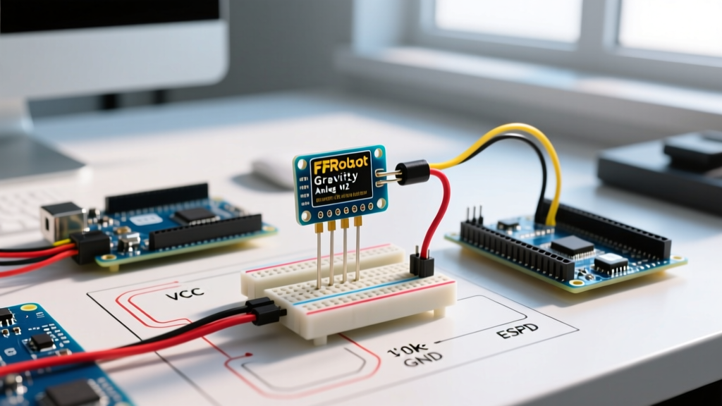
- VCC: Connect to the Arduino 5V pin. (If using an ESP32, use the 3V3 pin).
- GND: Connect to the Arduino GND pin. Keep this wire as short as physically possible to minimize ground loop impedance.
- A0 (Analog Out): Connect to Arduino Analog Pin A0.
- TO (Temperature Out): The V2 analog board does not process the internal thermistor. Leave this disconnected unless you are building a custom op-amp circuit to read it.
CRITICAL EXPERT WARNING: Never power a submersible water pump from the same breadboard power rail as your pH sensor. The electromagnetic interference (EMI) and back-EMF from the pump's motor will inject massive voltage spikes into your Arduino's ground plane, causing your analogRead() values to fluctuate wildly. Always use an isolated power supply or a relay/optocoupler for high-current peripherals.
Arduino C++ Code: Averaging and Mapping
Reading a pH sensor requires oversampling. A single Arduino analogRead() call is highly susceptible to transient electrical noise. The code below implements a 10-sample moving average and applies the DFRobot V2 linear regression formula.
// DFRobot Gravity Analog pH Sensor V2 - Precision Sampling Code
// Target: Arduino Uno / Mega / Nano (5V Logic)

const int pH_Pin = A0;
const int NumSamples = 10;
float Offset = 0.00; // Adjusted during calibration

void setup() {
  Serial.begin(9600);
  pinMode(pH_Pin, INPUT);
  Serial.println("pH Sensor V2 Initialized. Awaiting readings...");
}

void loop() {
  unsigned long int avgValue = 0;

  // Oversampling to filter high-frequency noise
  for (int i = 0; i < NumSamples; i++) {
    avgValue += analogRead(pH_Pin);
    delay(10); // 10ms settling delay between reads
  }

  // Calculate average analog value
  float avgAnalog = (float)avgValue / NumSamples;

  // Convert analog reading to voltage (assuming 5V reference, 10-bit ADC)
  float voltage = avgAnalog * 5.0 / 1024.0;

  // DFRobot V2 Linear Mapping Formula
  // The slope is approximately 3.5 for the V2 board's op-amp circuit
  float pHValue = 3.5 * voltage + Offset;

  Serial.print("Sensor Voltage: ");
  Serial.print(voltage, 3);
  Serial.print(" V  |  Calculated pH: ");
  Serial.println(pHValue, 2);

  delay(800); // Recommended polling interval for serial monitoring
}
Understanding the Math
The formula pH = 3.5 * voltage + Offset is derived from the operational amplifier circuit on the V2 board. The slope (3.5) is fixed by the hardware resistors. The Offset is a variable you determine during the calibration phase to account for minor manufacturing tolerances in the op-amp and the specific impedance of your E-201-C glass bulb.
The Two-Point Calibration Protocol
Out of the box, your pH sensor will not be perfectly accurate. You must perform a two-point calibration using standard buffer solutions. We recommend purchasing dry buffer powder packets (pH 4.01 and pH 6.86) and mixing them with precisely 250ml of distilled water.
- Preparation: Mix the 6.86 buffer powder into 250ml of distilled water. Stir until fully dissolved.
- Immersion: Submerge the E-201-C probe into the 6.86 solution. Ensure the glass bulb and the ceramic junction are fully covered.
- Stabilization: Wait 2 to 3 minutes. Watch the Serial Monitor. The voltage will drift as the glass membrane hydrates and equalizes. Wait until the voltage fluctuates by less than 0.01V over 10 seconds.
- Calculate Offset: Note the stable voltage. Use the algebraic inverse of the code's formula to find your offset:
Offset = 6.86 - (3.5 * measured_voltage). - Update Code: Hardcode this new
Offsetvalue into your Arduino sketch. - Verify (Optional): Rinse the probe with distilled water, submerge it in the 4.01 buffer, and verify the serial output reads between 3.95 and 4.05.
Edge Cases and Failure Modes
Even with perfect code, environmental factors will destroy your readings if ignored. Here are the most common failure modes encountered in the field.
1. The KCl Depletion Trap
The E-201-C probe contains a silver/silver-chloride reference electrode submerged in 3M KCl (Potassium Chloride) solution. Never store the probe in distilled or reverse osmosis (RO) water. Doing so causes osmosis to pull the KCl out of the probe, permanently ruining the reference junction. Always store the probe in the provided storage bottle filled with 3M KCl storage solution.
2. Temperature Compensation Blindspots
The pH of a liquid changes with temperature. The SEN0161 analog board does not feature Automatic Temperature Compensation (ATC). If your hydroponic reservoir swings from 18°C at night to 26°C during the day, your pH reading will drift by up to 0.15 pH units.
Solution: Integrate a waterproof DS18B20 temperature sensor into your Arduino build and apply the Nernst equation in your code to mathematically compensate the pH value based on real-time temperature.
3. Ceramic Junction Clogging
If you are measuring nutrient solutions with heavy organic compounds or particulate matter, the porous ceramic junction on the probe will clog, resulting in sluggish response times.
Solution: Soak the probe tip in a 0.1M HCl (Hydrochloric acid) solution for 10 minutes to dissolve organic blockages, then rinse and recalibrate.
Troubleshooting Matrix
| Symptom | Probable Cause | Corrective Action |
|---|---|---|
| Readings stuck at exactly 0.00 or 14.00 | Probe is completely dry or BNC connector is loose. | Soak probe in 3M KCl for 24 hours; tighten BNC threading. |
| Wild, random fluctuations (e.g., jumping 2.0 pH units) | Ground loop interference from nearby AC pumps or lighting. | Isolate pump power; add a 0.1µF ceramic capacitor between A0 and GND. |
| Readings drift continuously in one direction | Ceramic junction is clogged or KCl electrolyte is depleted. | Clean with 0.1M HCl; replace probe if internal fluid is clear instead of saturated. |
| Consistent offset across all buffer solutions | Incorrect ADC reference voltage assumption in code. | Measure Arduino 5V pin with a multimeter; update 5.0 in code to actual measured voltage (e.g., 4.85). |
Final Integration Thoughts
Building a robust pH sensor Arduino system requires looking beyond the basic wiring diagram. By implementing software oversampling, respecting the electrochemical limitations of the glass electrode, and isolating your analog ground from high-current peripherals, you can achieve lab-grade reliability in your DIY environmental monitors. For further hardware details and schematic diagrams, always refer to the official DFRobot SEN0161 Wiki.