
The Evolution of Silicon Temperature Sensing
When integrating a tmp sensor arduino project, engineers and hobbyists typically reach for the Texas Instruments TMP series. Unlike basic NTC thermistors that require complex Steinhart-Hart calculations and external voltage dividers, silicon bandgap temperature sensors output a highly linear, calibrated signal. Whether you are building a weather station, a 3D printer thermal management system, or a biotech incubator, choosing the right TMP sensor dictates your system's accuracy, resolution, and wiring complexity.
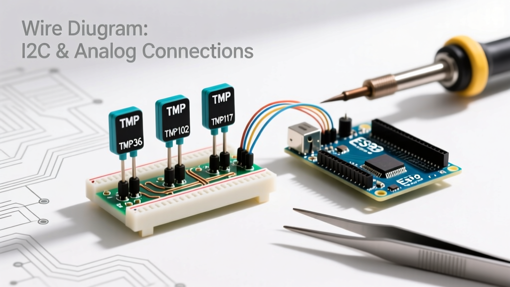
In this comprehensive integration guide, we will dissect three distinct architectures: the classic analog TMP36, the 12-bit digital TMP102, and the ultra-high-precision 16-bit TMP117. We will cover exact pinouts, I2C addressing, noise mitigation strategies, and provide production-ready Arduino C++ code.
Sensor Comparison Matrix: TMP36 vs TMP102 vs TMP117
Before routing traces on a PCB or wiring a breadboard, it is critical to select the correct silicon die for your application constraints. Below is a technical comparison of the three most common TMP sensors used in microcontroller ecosystems.
| Parameter | TMP36 (Analog) | TMP102 (Digital I2C) | TMP117 (Digital I2C) |
|---|---|---|---|
| Interface | Analog Voltage (10mV/°C) | I2C (SMBus compatible) | I2C (SMBus compatible) |
| Resolution | ADC Dependent (~4.8mV at 10-bit) | 12-bit (0.0625°C) | 16-bit (0.0078°C) |
| Accuracy (Typical) | ±1°C at 25°C | ±0.5°C (from -25 to +85°C) | ±0.1°C (from -20 to +50°C) |
| Operating Voltage | 2.7V to 5.5V | 1.4V to 3.6V | 1.8V to 5.5V |
| Quiescent Current | 50 µA | 10 µA (active), 1 µA (shutdown) | 3.5 µA (active), 125 nA (shutdown) |
| Approx. Cost (2026) | $1.50 - $2.50 | $2.00 - $3.50 | $4.00 - $6.50 |
Analog Integration: Wiring the TMP36
The TMP36 remains a staple in educational kits due to its 5V tolerance and simplicity. However, its analog nature makes it highly susceptible to electromagnetic interference (EMI) and ADC quantization noise.
Circuit Topology and Decoupling
The TMP36 features three pins: VCC, VOUT, and GND. The output voltage scales at exactly 10mV per degree Celsius, with a 500mV offset to allow for negative temperature readings without a dual-rail power supply.
- VCC: Connect to 5V (or 3.3V if using a 3.3V MCU, adjusting the ADC reference accordingly).
- GND: Connect to system ground.
- VOUT: Connect to an analog input pin (e.g., A0 on an Arduino Uno).
The TMP36 datasheet explicitly warns that capacitive loads greater than 1000pF on the output pin can cause the internal amplifier to oscillate, resulting in erratic, wildly fluctuating temperature readings. Never place a large filter capacitor directly on VOUT. Instead, place a 0.1µF ceramic decoupling capacitor directly across the VCC and GND pins as close to the sensor body as possible to reject power supply noise.
Digital I2C Integration: TMP102 and TMP117
For applications requiring high resolution or long wire runs, digital I2C sensors are mandatory. Analog signals degrade over distance, whereas I2C digital packets remain robust. The SparkFun TMP102 Hookup Guide highlights the ease of integrating these digital dies into embedded systems.
I2C Pull-Up Requirements and Addressing
Both the TMP102 and TMP117 utilize an open-drain I2C architecture. If you are using a bare IC rather than a breakout board, you must install 4.7kΩ pull-up resistors on both the SDA and SCL lines to the VCC rail. Without these, the I2C bus will float, causing the Arduino Wire library to hang indefinitely.
The TMP117 allows for hardware address configuration via the ADDR pin:
- ADDR to GND: I2C Address
0x48(Default) - ADDR to VCC: I2C Address
0x49 - ADDR to SDA: I2C Address
0x4A - ADDR to SCL: I2C Address
0x4B
This flexibility allows up to four TMP117 sensors on a single I2C bus, ideal for multi-zone thermal profiling in server racks or battery packs.
Arduino Code Implementation
Below are the optimized code structures for reading both the analog and digital variants. We utilize the standard Arduino Wire Library for the I2C communication.
TMP36 Analog Read with Software Oversampling
To mitigate ADC noise on the TMP36, we implement a software oversampling technique, taking 16 readings and averaging them before calculating the final temperature.
const int sensorPin = A0;

void setup() {
  Serial.begin(115200);
  analogReference(DEFAULT); // Use 5V reference on Uno
}

void loop() {
  long sum = 0;
  for(int i = 0; i < 16; i++) {
    sum += analogRead(sensorPin);
    delay(2); // Allow ADC S&H capacitor to settle
  }
  float avgReading = sum / 16.0;

  // Convert ADC value to voltage (assuming 5V reference, 10-bit ADC)
  float voltage = (avgReading * 5.0) / 1024.0;

  // TMP36 formula: Temp (°C) = (Voltage - 0.5) * 100
  float tempC = (voltage - 0.5) * 100.0;

  Serial.print("TMP36 Temp: ");
  Serial.print(tempC);
  Serial.println(" °C");

  delay(1000);
}
TMP117 High-Precision I2C Read
The TMP117 outputs a 16-bit signed integer. According to the Texas Instruments TMP117 Datasheet, the LSB represents exactly 0.0078125°C. This code reads the raw register and applies the conversion factor.
#include <Wire.h>

#define TMP117_ADDR 0x48
#define TEMP_REG 0x00

void setup() {
  Wire.begin();
  Serial.begin(115200);

  // Verify sensor presence
  Wire.beginTransmission(TMP117_ADDR);
  if (Wire.endTransmission() != 0) {
    Serial.println("FATAL: TMP117 not found on I2C bus!");
    while(1);
  }
}

void loop() {
  Wire.beginTransmission(TMP117_ADDR);
  Wire.write(TEMP_REG); // Point to Temperature Register
  Wire.endTransmission(false); // Repeated start condition

  Wire.requestFrom(TMP117_ADDR, 2);
  if (Wire.available() == 2) {
    int16_t rawTemp = (Wire.read() << 8) | Wire.read();
    float tempC = rawTemp * 0.0078125;

    Serial.print("TMP117 High-Res Temp: ");
    Serial.print(tempC, 4); // Print 4 decimal places
    Serial.println(" °C");
  }

  delay(1000);
}
Edge Cases: Thermal Lag and Self-Heating
A common failure mode in precision thermal design is self-heating error. The electrical current consumed by the sensor's internal circuitry dissipates power as heat, slightly raising the temperature of the silicon die above the ambient environment.
"In still air, the TMP117's self-heating error is negligible due to its ultra-low 3.5 µA active current. However, if the sensor is continuously polled at high speeds, the internal digital logic generates excess thermal noise. Utilizing the sensor's One-Shot conversion mode via the configuration register reduces average power consumption to nano-amp levels, virtually eliminating self-heating in stagnant air environments."
Thermal Lag: The TO-92 package (common for TMP36) and SOT-563 package (TMP117) have different thermal mass. If you are measuring rapidly changing fluid temperatures, the epoxy encapsulation will introduce a time constant (lag) of 2 to 5 seconds. For fluid dynamics, always use a thermally conductive potting compound or a specialized stainless-steel probe housing rather than a bare PCB mount.
Frequently Asked Questions
Can I use a TMP36 with a 3.3V Arduino (like the ESP32 or Due)?
Yes, the TMP36 operates down to 2.7V. However, you must adjust your code's ADC reference calculation. If your ESP32 uses a 3.3V reference and a 12-bit ADC (0-4095), the voltage formula becomes (reading * 3.3) / 4095.0. Note that ESP32 ADCs are notoriously non-linear at the extreme ends of the voltage rail; for 3.3V systems, the digital TMP117 is highly recommended over the analog TMP36.
Why is my TMP102 returning a constant -127°C or 255°C?
This indicates an I2C communication failure. The Arduino is reading 0xFF or 0x00 from the bus because the sensor is not acknowledging. Check for missing 4.7kΩ pull-up resistors, verify the ADDR pin is pulled to GND for the default 0x48 address, and ensure your logic levels match (a 5V Arduino Uno requires a logic level shifter to safely interface with the 3.3V TMP102 without risking die degradation over time).