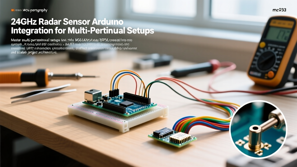

The Evolution of Presence Detection: Why 24GHz mmWave Dominates in 2026
When designing a smart room node, integrating a radar sensor Arduino setup with secondary peripherals like OLED displays and relays introduces complex architectural challenges. For years, makers relied on Passive Infrared (PIR) sensors like the HC-SR501 or microwave Doppler modules like the RCWL-0516. However, PIR sensors fundamentally fail at static presence detection because they rely on the pyroelectric effect—requiring a delta-T (temperature change) movement across their Fresnel lenses. If a human sits still reading a book, the PIR turns off.
Enter the 24GHz Frequency Modulated Continuous Wave (FMCW) radar. Modules like the Hi-Link HLK-LD2410 emit millimeter waves that detect micro-movements, including the expansion and contraction of a human chest cavity during breathing. As of 2026, the LD2410 has become the undisputed standard for DIY presence detection, offering configurable detection 'gates' and precise distance reporting via UART. But integrating this high-frequency RF module alongside I2C displays and inductive relay loads requires strict adherence to power management and signal integrity protocols.
Multi-Peripheral BOM and 2026 Pricing Matrix
Building a robust multi-sensor node requires balancing cost, logic levels, and power draw. Below is the verified Bill of Materials (BOM) for a fully integrated presence and control node, reflecting early 2026 market pricing from major distributors.
| Component | Model / Specification | Interface | Logic Level | Est. Price (2026) |
|---|---|---|---|---|
| Microcontroller | Arduino Uno R4 Minima | USB / GPIO | 5V | $27.50 |
| Radar Sensor | Hi-Link HLK-LD2410 | UART (TX/RX) | 3.3V | $5.80 |
| Display | SSD1306 128x64 OLED | I2C (SDA/SCL) | 3.3V - 5V | $3.50 |
| Actuator Control | 5V Opto-Isolated Relay | GPIO (Digital) | 5V Trigger | $2.80 |
| Power Conditioning | 470µF Electrolytic Cap | Power Rail | N/A | $0.45 |
Hardware Architecture: Resolving UART and I2C Conflicts
The most common point of failure in multi-peripheral Arduino setups is interface contention. The HLK-LD2410 communicates exclusively via UART at a default baud rate of 256,000. Older 8-bit boards like the Arduino Uno R3 only possess a single hardware UART tied to the USB-to-Serial chip, forcing developers to use SoftwareSerial. Bit-banging UART at 256,000 baud on a 16MHz ATmega328P results in massive packet loss and CPU blocking.
The Uno R4 Minima Advantage
By utilizing the Arduino Uno R4 Minima (based on the Renesas RA4M1 ARM Cortex-M4), we gain a dedicated hardware Serial1 on pins 0 (RX) and 1 (TX) that is entirely independent of the native USB CDC serial port. This allows you to debug via the USB serial monitor while simultaneously maintaining a rock-solid 256,000 baud hardware connection to the radar sensor. According to the official Arduino Serial reference documentation, leveraging hardware UART buffers is mandatory for high-speed sensor telemetry to prevent buffer overflow.
I2C Bus Capacitance and Pull-Up Resistors
While the radar occupies the UART lines, the SSD1306 OLED display utilizes the I2C bus (A4/SDA and A5/SCL on the R4 Minima). When combining multiple I2C peripherals, bus capacitance increases, which can degrade the square wave signal edges. The SSD1306 breakout boards typically include 4.7kΩ pull-up resistors. If you plan to add an I2C environmental sensor (like a BME280) later, the parallel resistance will drop to roughly 2.35kΩ, which is generally acceptable for 100kHz I2C but may cause issues at 400kHz. Always verify your I2C address map using the Adafruit I2C address master list to ensure no hex-address collisions occur between your display and future sensors.
Critical Wiring: Voltage Level Shifting for 3.3V Logic
A fatal mistake made by beginners is wiring the 5V TX pin of an Arduino directly into the 3.3V RX pin of the HLK-LD2410. While the LD2410's VCC pin accepts 5V to power its internal LDO, its data pins are strictly 3.3V tolerant. Feeding 5V logic into the radar's RX pin will degrade the internal RF transceiver IC over time or destroy it instantly.
The Voltage Divider Solution:
You must step down the Arduino's 5V TX (Pin 1) to a safe 3.3V logic level using a simple resistor voltage divider. Using a 2kΩ resistor (R1) in series with the signal and a 3.3kΩ resistor (R2) to ground yields the following output:
V_out = V_in × (R2 / (R1 + R2))
V_out = 5V × (3300 / (2000 + 3300)) = 3.11V3.11V is well within the safe logic-HIGH threshold for the LD2410's RX pin, ensuring reliable UART handshakes without risking silicon damage.
Wiring Map:
- LD2410 VCC -> Arduino 5V
- LD2410 GND -> Arduino GND
- LD2410 TX -> Arduino Pin 0 (RX) (Direct connection, 3.3V is read as HIGH by 5V ARM logic)
- LD2410 RX -> Voltage Divider Midpoint (Stepped down from Arduino Pin 1 TX)
Power Rail Management and Brownout Prevention
In a multi-peripheral setup, transient current spikes are the enemy of RF sensitivity. The HLK-LD2410 draws roughly 70mA during active transmission. The SSD1306 draws about 20mA. However, when the 5V opto-isolated relay module engages, its coil demands an instantaneous spike of 70mA to 90mA.
If these components share the same thin breadboard power rails, the voltage drop (brownout) caused by the relay coil energizing can starve the radar sensor. This causes the LD2410 to reset, dropping the UART connection and resulting in 'ghosting' or false-negative presence readings.
The Capacitor Fix
To stabilize the local power rail, solder a 470µF electrolytic capacitor directly across the 5V and GND pins on the breadboard rail nearest to the radar and relay. This capacitor acts as a local energy reservoir, supplying the instantaneous current required by the relay coil without pulling the voltage down on the main microcontroller rail. Furthermore, ensure your relay module features an opto-isolator (like the PC817) and a flyback diode to prevent inductive kickback from traveling back into the Arduino's GPIO pin.
State Machine Logic for Sensor Fusion
Raw radar data is noisy. To create a reliable multi-peripheral node, you must implement a state machine that fuses the radar's 'Target Distance' and 'Target Energy' metrics before triggering the relay or updating the OLED display.
Do not simply toggle a relay the millisecond the radar reports presence. Implement a temporal filter:
- State 0 (Vacant): Radar reports 0 targets. Relay is OFF. OLED shows 'Room Empty'.
- State 1 (Pending Verification): Radar detects energy > 20% at a distance < 4 meters. Start a 500ms debounce timer. Do not trigger relay yet.
- State 2 (Occupied): Timer expires and target remains. Trigger Relay HIGH. Update OLED with exact distance (e.g., 'Occupied: 1.4m').
- State 3 (Static Hold): Radar detects micro-movements (breathing). Reset the 'Vacant' timeout counter to 10 minutes.
This logic prevents the relay from rapidly clicking on and off if a pet walks through the room or if a ceiling fan triggers a momentary multipath reflection.
Troubleshooting Multipath Interference and Ghosting
24GHz mmWave signals behave like light; they reflect off hard surfaces. In a multi-peripheral node placed in the corner of a room, the radar may detect the reflection of a person walking in an adjacent hallway through a closed wooden door, or bounce off a spinning HVAC ceiling fan.
Edge Case Resolution:
- Gate Configuration: Use the manufacturer's UART configuration commands to limit the 'Max Detection Gate'. If your desk is 2 meters from the wall, configure the radar to ignore all returns beyond Gate 4 (approx. 3 meters). This eliminates hallway ghosting.
- Static Clutter Removal: The LD2410 features a background noise calibration command. Trigger this command via your Arduino setup routine (or a dedicated push-button peripheral) when the room is physically empty. This maps the static reflections of furniture and walls as baseline noise, drastically improving human-to-clutter signal-to-noise ratio (SNR).
- RF Shielding: Keep the radar module at least 3cm away from the OLED display's I2C ribbon cable and the relay's copper coil to prevent localized electromagnetic interference (EMI) from desensitizing the patch antenna.
Authoritative Resources and Safety Standards
When deploying 24GHz RF transmitters in residential or commercial environments, it is important to understand the regulatory and safety landscape. The FMCW radar modules operate at extremely low power levels (typically under 10dBm), making them entirely safe for continuous human exposure. For comprehensive data on RF emission safety limits and exposure guidelines, refer to the Federal Communications Commission (FCC) Radio Frequency Safety guidelines.
By respecting logic-level boundaries, stabilizing your power rails against inductive kickback, and implementing temporal debouncing in your firmware, your radar sensor Arduino setup will transition from a fragile breadboard experiment into a robust, production-ready multi-peripheral automation node.