
Why I2C is the Standard for LCD Arduino Sensor Projects
When building standalone environmental monitoring stations or DIY smart home nodes, relying on the Serial Monitor for debugging is a major bottleneck. Transitioning to a standalone display requires mastering the LCD Arduino interface. While the classic parallel HD44780 16x2 display requires six digital pins for data and control, modern makers almost exclusively use an I2C backpack. This reduces the wiring footprint to just two data lines (SDA and SCL), freeing up critical GPIO pins for additional sensors, relays, or motor controllers.
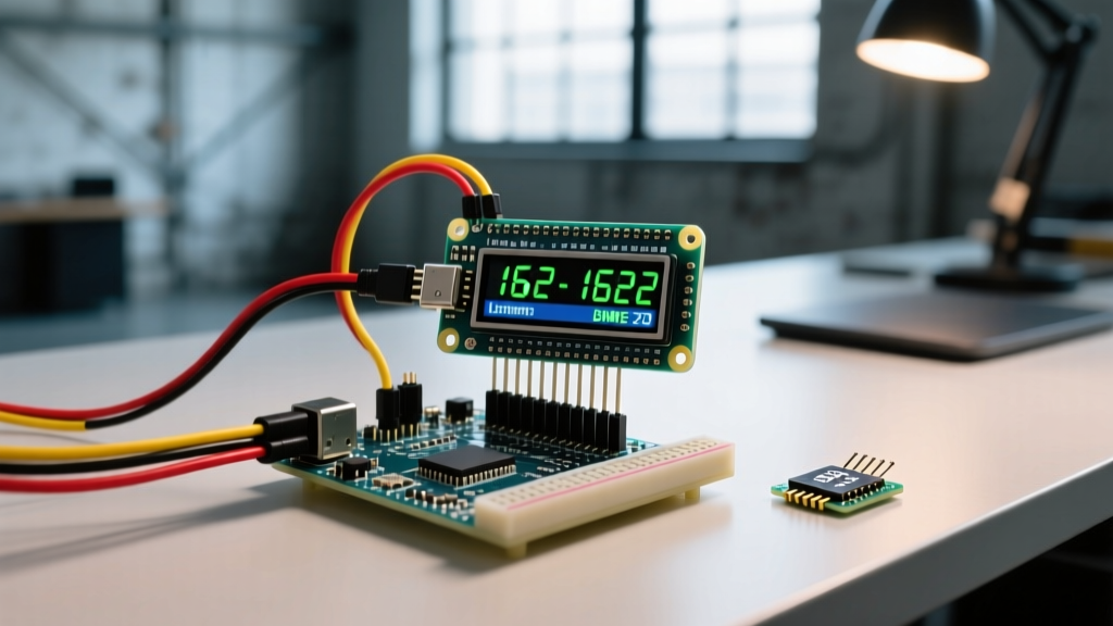
In this tutorial, we will integrate a 16x2 I2C LCD with an Arduino Uno R4 Minima and a Bosch BME280 environmental sensor. We will cover hardware wiring, the notorious I2C address conflict trap, custom character generation for temperature readouts, and advanced bus capacitance troubleshooting.
2026 Hardware Bill of Materials (BOM)
Component pricing and availability have stabilized in 2026. The Arduino Uno R4 Minima is now the standard recommendation over the legacy R3 due to its 32-bit ARM Cortex-M4 processor, which handles I2C bus interrupts and floating-point sensor math significantly faster.
| Component | Specific Model / IC | Est. Price (2026) | Role |
|---|---|---|---|
| Microcontroller | Arduino Uno R4 Minima | $22.50 | Main logic and I2C master |
| Display | 16x2 LCD with PCF8574 I2C Backpack | $6.00 - $8.50 | Visual telemetry output |
| Sensor | Bosch BME280 Breakout (I2C) | $8.00 - $12.00 | Temp, Humidity, Pressure |
| Resistors | 2.2kΩ or 4.7kΩ Pull-ups (x2) | $0.10 | I2C bus signal stabilization |
Wiring Matrix: Uno R4, BME280, and 16x2 LCD
Because both the LCD backpack and the BME280 sensor utilize the I2C protocol, they share the same bus lines. This is the primary advantage of the LCD Arduino I2C architecture: you can daisy-chain dozens of devices on the same two wires, provided their addresses do not conflict.
Pinout Configuration
- VCC (LCD & BME280): Connect to 5V on the Uno R4. (Note: Ensure your specific BME280 breakout has an onboard voltage regulator. Raw Bosch BME280 chips are 3.3V logic, but standard maker breakouts include a 3.3V LDO).
- GND (LCD & BME280): Connect to common ground.
- SDA (LCD & BME280): Connect to A4 (or the dedicated SDA pin near the AREF header).
- SCL (LCD & BME280): Connect to A5 (or the dedicated SCL pin).
Critical Failure Mode: The I2C Address Trap
The most common reason an LCD Arduino project fails silently—where the code compiles, uploads, but the screen remains blank—is an I2C address mismatch. The I2C backpacks soldered onto 16x2 LCDs use an NXP or Texas Instruments I/O expander chip to translate I2C serial data into parallel HD44780 signals.
⚠️ The PCF8574T vs. PCF8574AT Problem:
Backpacks using the PCF8574T chip have a default I2C address of0x27. However, many manufacturers silently substitute the PCF8574AT chip due to supply chain fluctuations. The 'AT' variant has a default address of0x3F. If your code initializesLiquidCrystal_I2C lcd(0x27, 16, 2);but your hardware is 0x3F, the display will not respond.
Always verify your hardware address before writing display logic. You can cross-reference known defaults on Adafruit's comprehensive I2C address list, or run a basic I2C Scanner sketch from the Arduino Wire Library documentation to poll the bus and print the active hex addresses to your Serial Monitor.
Firmware Integration: Displaying Sensor Telemetry
To display data from the BME280, we use the Adafruit_BME280 library alongside the LiquidCrystal_I2C library. A common beginner mistake is using delay(2000) to pause between screen updates. This blocks the microcontroller, causing I2C bus timeouts and preventing background tasks from running.
Instead, use a non-blocking millis() timer approach.
Generating the Degree Symbol (Custom Characters)
The standard HD44780 ROM (specifically the A00 variant found on 95% of displays) does not include the degree symbol (°) in its character map. Attempting to print it via standard UTF-8 will result in garbled Japanese characters or empty blocks. You must manually define the degree symbol in the LCD's CGRAM (Character Generator RAM) using a byte array.
#include <Wire.h>
#include <LiquidCrystal_I2C.h>
#include <Adafruit_BME280.h>

// Initialize LCD at address 0x27 (Change to 0x3F if using PCF8574AT)
LiquidCrystal_I2C lcd(0x27, 16, 2);
Adafruit_BME280 bme;

// Custom Degree Symbol Byte Array
byte degreeSymbol[8] = {
  0b00110,
  0b01001,
  0b01001,
  0b00110,
  0b00000,
  0b00000,
  0b00000,
  0b00000
};

unsigned long lastUpdate = 0;
const long interval = 2000;

void setup() {
  Serial.begin(115200);
  lcd.init();
  lcd.backlight();
  lcd.createChar(0, degreeSymbol);

  if (!bme.begin(0x76)) { // BME280 default is often 0x76 or 0x77
    Serial.println("BME280 Sensor Not Found!");
    while (1);
  }

  lcd.setCursor(0, 0);
  lcd.print("System Online...");
  delay(1000);
  lcd.clear();
}

void loop() {
  unsigned long currentMillis = millis();
  if (currentMillis - lastUpdate >= interval) {
    lastUpdate = currentMillis;
    updateDisplay();
  }
}

void updateDisplay() {
  float temp = bme.readTemperature();
  float hum = bme.readHumidity();

  lcd.setCursor(0, 0);
  lcd.print("Temp: ");
  lcd.print(temp, 1);
  lcd.write((byte)0); // Print custom degree symbol
  lcd.print("C    ");

  lcd.setCursor(0, 1);
  lcd.print("Hum:  ");
  lcd.print(hum, 1);
  lcd.print("%    ");
}
Advanced Troubleshooting: Bus Capacitance and Contrast
Even with perfect code and correct I2C addresses, physical hardware anomalies can disrupt your LCD Arduino build. Here are the two most frequent edge cases encountered in the field:
1. The Contrast Potentiometer Illusion
If your LCD backlight turns on (glowing blue or green) but the screen appears completely blank, or conversely, shows a solid row of white rectangles on the top line, your code is likely working perfectly. The issue is the V0 contrast pin. On the back of the I2C backpack, there is a small blue trimmer potentiometer. Use a small Phillips screwdriver to turn it clockwise or counter-clockwise until the 5x8 pixel character blocks become sharply visible against the background.
2. I2C Bus Capacitance and Signal Degradation
I2C is an open-drain communication protocol. It relies on pull-up resistors to bring the voltage back to HIGH (5V) after a device pulls the line LOW. The wires in your circuit act as tiny capacitors. According to the Bosch Sensortec BME280 datasheet and standard I2C specifications, the maximum allowable bus capacitance is 400pF for standard 100kHz mode.
If you are using jumper wires longer than 30cm to route your LCD to a project enclosure, the parasitic capacitance increases. This causes the rising edges of the I2C square wave to slope upwards rather than snapping sharply to 5V, resulting in data corruption or dropped frames.
- The Fix: Most Arduino boards have internal 20kΩ-50kΩ pull-ups, which are far too weak for long wires. Solder external 2.2kΩ pull-up resistors between the SDA/SCL lines and the 5V rail. The lower resistance provides more current to charge the parasitic wire capacitance rapidly, restoring crisp signal edges.
Summary
Integrating an I2C display into your sensor projects transforms a breadboard prototype into a finished, user-facing appliance. By understanding the nuances of I2C addressing, managing CGRAM for custom telemetry symbols, and respecting the electrical physics of bus capacitance, you ensure your LCD Arduino builds remain robust, responsive, and professional.