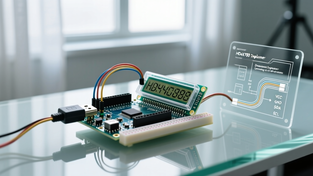

The Heart of the Display: HD44780U Controller Overview
When you search for an lcd with arduino, you are almost certainly looking at a display driven by the Hitachi HD44780U controller or one of its modern silicon clones, such as the Sunplus SPLC780D or Wuxi AIP31068. Originally released in the late 1990s, this controller remains the undisputed standard for character LCDs in 2026. A standard 16x2 parallel module costs between $2.50 and $4.00, while I2C-equipped variants range from $3.50 to $5.50.
However, most hobbyists rely blindly on the LiquidCrystal library without understanding the underlying hardware. By reading the actual Hitachi HD44780 Datasheet, we can uncover why certain displays glitch, why timing delays are necessary, and how to optimize memory mapping for custom layouts.
Pinout Translation: Datasheet vs. Arduino Reality
The HD44780 uses a 16-pin parallel interface. While the datasheet lists functional names, mapping these to an Arduino Uno (ATmega328P) or Nano requires understanding voltage tolerances and internal pull-up behaviors. Below is the definitive translation matrix for a 4-bit mode implementation, which is the industry standard for saving GPIO pins.
| Pin # | Datasheet Name | Arduino Pin (Example) | Function & Datasheet Notes |
|---|---|---|---|
| 1 | VSS | GND | Ground reference (0V). |
| 2 | VDD | 5V | Logic power supply. Warning: 3.3V MCUs require a logic level shifter or a 3.3V-specific LCD. |
| 3 | V0 | Potentiometer Wiper | Contrast control. Requires 0V to 0.5V. Tying directly to GND works on many modern high-efficiency screens. |
| 4 | RS | D12 | Register Select. 0 = Instruction Register, 1 = Data Register. |
| 5 | R/W | GND | Read/Write. Always tie to GND unless you are reading the busy flag (rare in Arduino applications). |
| 6 | E | D11 | Enable. A falling edge triggers data latching. |
| 11-14 | DB4 - DB7 | D5, D4, D3, D2 | 4-bit data bus. DB0-DB3 (Pins 7-10) are left unconnected. |
| 15 | A | 5V (via 100Ω) | Backlight Anode. The datasheet specifies a forward voltage of ~4.2V; a current-limiting resistor is mandatory. |
| 16 | K | GND | Backlight Cathode. |
Deciphering the Timing Diagrams (The Hidden Gotchas)
The most common reason a custom bit-banged LCD implementation fails is a misinterpretation of the datasheet's AC timing characteristics. The Arduino LiquidCrystal Reference handles this via software delays, but understanding the hardware limits is crucial for optimization.
Enable (E) Pulse Width and Setup Times
According to the datasheet, the Enable pin requires a minimum pulse width ($t_{PW}$) of 450 nanoseconds. The data setup time ($t_{AS}$) is 60ns, and the hold time ($t_{AH}$) is 10ns. On a 16MHz Arduino Uno, a single digitalWrite() function call takes approximately 3 to 4 microseconds (3000-4000ns). Therefore, the Arduino's inherent software overhead naturally satisfies the 450ns pulse width requirement without needing explicit delayMicroseconds() calls for the pulse itself.
However, if you are using direct port manipulation (e.g., PORTD |= B00001000;) on a faster microcontroller like the Teensy 4.1 (600MHz), you must insert a deliberate delay to stretch the pulse, or the LCD will miss the data entirely.
Command Execution Times: The 1.52ms Trap
Not all commands are created equal. The datasheet specifies two distinct execution times:
- Standard Commands (e.g., Cursor Move, Write Data): 37 microseconds.
- Clear Display (0x01) and Return Home (0x02): 1.52 milliseconds.
Pro-Tip: Many novice developers use a blanketdelay(2)after every command. By checking the Busy Flag (BF) on Pin 5 (if R/W is used) or applying a targeteddelayMicroseconds(1600)exclusively afterlcd.clear(), you can reclaim 1.48ms of processing time per clear command—critical for high-speed data logging applications.
DDRAM vs. CGROM: Memory Mapping Explained
To write text, you must understand Display Data RAM (DDRAM). The HD44780 contains 80 bytes of DDRAM, but it is not mapped linearly to the physical screen in the way most programmers assume.
The Hex Address Matrix
When you send a command to set the cursor, you are actually sending a DDRAM address. The datasheet reveals the following memory map:
- Line 1: 0x00 to 0x0F (for 16x2) or 0x00 to 0x13 (for 20x4)
- Line 2: 0x40 to 0x4F (for 16x2) or 0x40 to 0x53 (for 20x4)
- Line 3 (20x4 only): 0x14 to 0x27
- Line 4 (20x4 only): 0x54 to 0x67
Notice the gap between 0x0F and 0x40. If you continuously write data past the 16th character on Line 1 without issuing a new line command, the text will disappear into the "void" of the unconnected DDRAM addresses (0x10 to 0x3F) before reappearing on Line 2 at 0x40. This is a frequent source of confusion for developers attempting to create scrolling marquee effects.
CGROM and Custom Characters
The Character Generator ROM (CGROM) contains 208 standard 5x8 dot patterns. However, the Character Generator RAM (CGRAM) allows you to define up to 8 custom characters (addresses 0x00 to 0x07). To upload a custom character, you must switch the RS pin HIGH, set the CGRAM address, and push 8 bytes of bitmap data. Once stored, you print them to the DDRAM just like standard ASCII characters.
The I2C Backpack Alternative: PCF8574T Expander
Wiring 6 GPIO pins for a parallel LCD is impractical for modern IoT projects using ESP32 or Raspberry Pi Pico W microcontrollers, where pins are at a premium. The industry solution is the I2C backpack, typically based on the NXP/TI PCF8574 or PCF8574A I/O expander.
The 0x27 vs. 0x3F Address Dilemma
A massive pain point in the Arduino community is I2C address conflicts. The datasheet for the PCF8574 I2C Expander dictates that the base address is determined by the A0, A1, and A2 pins.
- PCF8574T (Texas Instruments / NXP): Base address is
0x20. With A0-A2 tied HIGH (default on most backpacks), the address shifts to 0x27. - PCF8574AT (NXP specific variant): Base address is
0x38. With A0-A2 tied HIGH, the address shifts to 0x3F.
If your I2C_Scanner sketch returns 0x3F but your LiquidCrystal_I2C library is hardcoded to 0x27, your display will remain blank. Always verify the exact silicon manufacturer stamped on the backpack IC.
Real-World Failure Modes & Datasheet Fixes
Even with perfect code, hardware edge cases will ruin your day. Here are three specific failure modes derived from the electrical characteristics section of the datasheet, and how to fix them.
1. The "Ghosting" Effect on Floating Pins
Symptom: Random blocks or faint characters appear on the screen, especially when nearby relays switch or motors spin. Datasheet Cause: The DB0-DB3 pins (in 4-bit mode) or the R/W pin are left floating. CMOS inputs have extremely high impedance and will act as antennas for EMI. Fix: Tie all unused data pins (DB0-DB3) and the R/W pin directly to GND. Do not leave them unconnected.
2. Contrast Drift in High-Temperature Environments
Symptom: The display is perfectly readable at 22°C, but turns completely black or completely blank when placed in an outdoor enclosure at 45°C. Datasheet Cause: The V0 contrast pin requires a specific voltage relative to VDD, and the liquid crystal fluid's optical threshold shifts with temperature (typically -3mV/°C). Fix: Replace the standard 10kΩ trimpot with a negative-temperature-coefficient (NTC) thermistor network, or use an Arduino PWM pin with an RC low-pass filter to dynamically adjust the V0 voltage based on a thermistor reading.
3. Logic Level Mismatch (The 3.3V Killer)
Symptom: The LCD works intermittently with an ESP32-C6 or Raspberry Pi Pico, and eventually the microcontroller's GPIO pin burns out. Datasheet Cause: The HD44780U requires a minimum $V_{IH}$ (High-level input voltage) of 2.2V (when VDD=5V), which a 3.3V MCU can barely provide. Worse, if the LCD's internal pull-ups or backlight circuitry back-feeds 5V into the 3.3V MCU pin, it exceeds the absolute maximum ratings. Fix: Use a dedicated 3.3V LCD module (which has an internal charge pump for the contrast) or route the signals through a bidirectional logic level shifter like the BSS138 MOSFET circuit.
Summary
Interfacing an LCD with an Arduino is a rite of passage, but treating the HD44780 as a black box limits your capabilities. By respecting the nanosecond timing requirements, understanding the non-linear DDRAM hex mapping, and properly managing I2C expander addresses, you transition from simply copying tutorials to engineering robust, production-ready embedded displays.