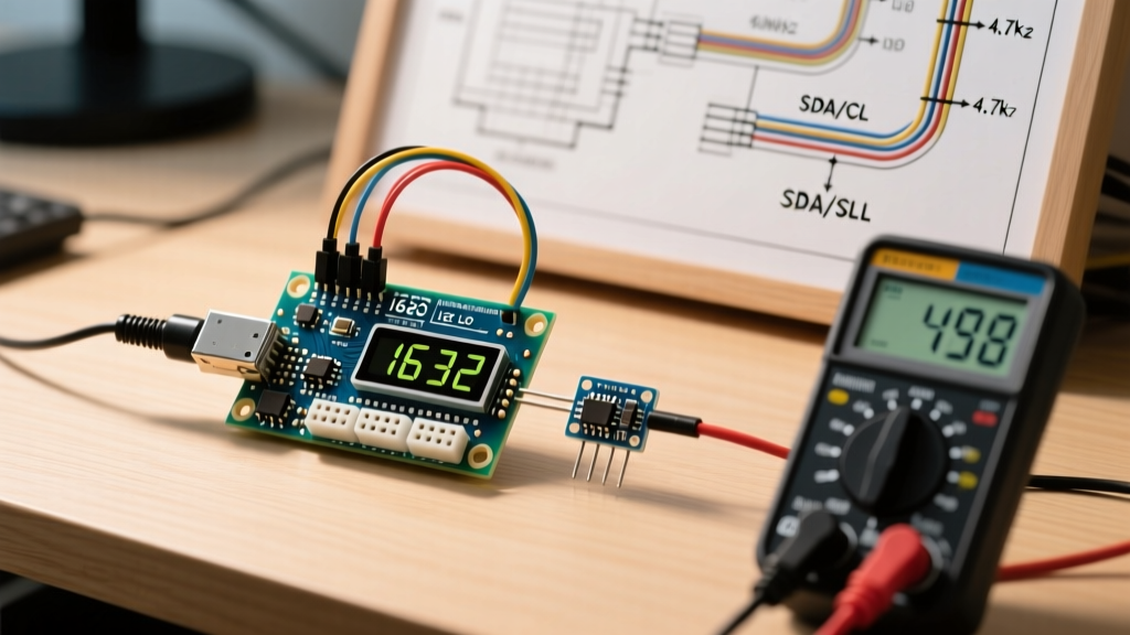

The Hidden Inaccuracies in Arduino LCD Sensor Displays
When integrating sensors with a microcontroller, the display is your only window into the system's reality. However, many makers wire an Arduino with LCD modules only to find that the displayed temperature, voltage, or pressure readings fluctuate wildly or drift over time. Is the sensor failing? Is the code flawed? More often than not, the inaccuracy stems from uncalibrated hardware interfaces and poor analog-to-digital conversion (ADC) practices.
In 2026, with the widespread adoption of the Arduino Uno R4 Minima and WiFi boards featuring 14-bit ADCs, alongside legacy ATmega328P boards, achieving laboratory-grade accuracy on a standard 16x2 or TFT LCD requires deliberate calibration. This guide bypasses basic wiring tutorials and dives deep into the electrical and software calibration techniques required to ensure your Arduino with LCD setup displays precision sensor data.
Hardware Calibration: I2C Signal Integrity and Contrast Tuning
Before writing a single line of C++, you must calibrate the physical layer. Most modern character LCDs use an I2C backpack (like the PCF8574T) to save GPIO pins. This introduces bus capacitance and signal degradation risks.
1. I2C Pull-Up Resistor Tuning
The I2C protocol relies on open-drain lines pulled high by resistors. The standard Arduino I2C bus uses internal pull-ups of roughly 20kΩ to 50kΩ, which are far too weak for the high capacitance introduced by LCD backpacks and jumper wires. According to the official NXP I2C-bus specification (UM10204), the bus capacitance must not exceed 400pF for standard-mode (100kHz) operation.
- Standard 16x2 LCD Backpack: Adds approximately 15pF to 25pF of capacitance.
- Long Jumper Wires (>15cm): Can add 2pF to 3pF per centimeter.
Calibration Action: If your LCD exhibits ghosting, random character blocks, or fails to initialize when using long wires, disable internal pull-ups and solder external 4.7kΩ pull-up resistors to both SDA and SCL lines. If you are pushing the bus to 400kHz (Fast-mode), drop the pull-ups to 2.2kΩ to sharpen the signal rise times.
2. The V0 Contrast Voltage Calibration
Eyeballing the blue trimpot on the back of an HD44780 LCD is a recipe for poor optical contrast and thermal drift. As the ambient temperature changes, the liquid crystal threshold voltage shifts.
Pro-Tip: Do not adjust the trimpot while the backlight is off. Power the LCD with the backlight ON, connect a multimeter to the V0 pin and VSS (Ground), and adjust the trimpot until the voltage reads exactly 0.45V to 0.55V. This specific range yields the highest contrast ratio without inducing 'ghost' characters in the background grid.
Software Calibration: ADC Accuracy and Reference Voltages
Your Arduino with LCD is only as accurate as the analog readings it processes. By default, the Arduino uses the USB VCC (nominally 5V) as the ADC reference. However, USB power from a standard PC hub or wall wart can fluctuate between 4.75V and 5.25V. A 5% fluctuation in VCC directly translates to a 5% error in your sensor readings.
Locking the Analog Reference
To eliminate VCC noise, you must switch the ADC reference to the microcontroller's internal bandgap voltage. As detailed in the Arduino analogReference() documentation, using the internal reference decouples your ADC from USB power noise.
// For ATmega328P (Uno R3, Nano)
analogReference(INTERNAL); // Locks reference to internal 1.1V bandgap

// For Arduino Uno R4 (RA4M1)
analogReference(AR_INTERNAL1V5); // Locks reference to 1.5V or 2.5V
Crucial Warning: Once you switch to the INTERNAL reference, your analog input pins must never see a voltage higher than the internal reference (e.g., 1.1V on the Uno R3). You must use a precision resistor voltage divider to step down 5V sensor outputs to the 1.1V range before they reach the Arduino.
Algorithmic Calibration: ADC Oversampling
If you need more resolution than the native 10-bit (1024 steps) of the ATmega328P, you can use oversampling. By taking multiple samples and bit-shifting, you can artificially increase the ADC resolution. According to the Microchip ATmega328P Datasheet, thermal noise in the silicon actually aids this process.
unsigned int readOversampledADC(int pin) {
  unsigned long sum = 0;
  // Read 16 times to gain 2 extra bits of resolution (10-bit -> 12-bit)
  for (int i = 0; i < 16; i++) {
    sum += analogRead(pin);
    delayMicroseconds(200); // Allow sample-and-hold capacitor to settle
  }
  return (sum >> 2); // Divide by 4 (right shift 2) to scale back to 12-bit
}
Displaying this 12-bit calibrated data on your LCD will drastically smooth out the 'jitter' seen in the least significant digits of temperature or voltage readings.
Display Refresh Calibration: Eliminating Flicker and Tearing
A major accuracy illusion occurs when an LCD flickers during updates, causing the human eye to misread digits. The novice approach is calling lcd.clear() inside the main loop. This forces the display controller to blank the entire RAM buffer, resulting in a 2ms to 5ms flicker and blocking the MCU from reading sensors.
The Delta-Update Technique
To maintain a rock-solid display, only overwrite the exact characters that have changed. This requires formatting the string in memory and writing it to specific cursor coordinates.
float previousTemp = 0.0;
char lcdBuffer[8];

void updateDisplay(float currentTemp) {
  // Only update LCD if value changes beyond our noise threshold (0.05)
  if (abs(currentTemp - previousTemp) >= 0.05) {
    lcd.setCursor(10, 0); // Target exact column/row
    sprintf(lcdBuffer, "%5.1f", currentTemp); // Format with padding
    lcd.print(lcdBuffer);
    previousTemp = currentTemp;
  }
}
This delta-update method ensures the Arduino with LCD setup remains responsive, freeing up thousands of CPU cycles per second for advanced sensor filtering algorithms like Kalman or moving-average filters.
Component Comparison Matrix: LCD Calibration Profiles
Different display technologies require entirely different calibration focuses. Below is a 2026 market breakdown of common displays paired with Arduino boards.
| Display Type | Interface | Primary Calibration Focus | Bus Capacitance Limit | Avg 2026 Price |
|---|---|---|---|---|
| 16x2 Character (HD44780) | I2C (PCF8574) | V0 Voltage (0.5V), I2C Pull-ups | 400pF | $6.50 - $9.00 |
| 128x64 Graphic OLED (SSD1306) | I2C / SPI | Contrast Register (0x81), SPI Clock Phase | 400pF (I2C) | $4.00 - $7.50 |
| 2.4" TFT LCD (ILI9341) | SPI (4-Wire) | Gamma Correction Registers, SPI Speed | N/A (Push-Pull SPI) | $12.00 - $18.00 |
| Nextion HMI (NX4024T032) | UART (Serial) | Baud Rate Sync, Touch Matrix Calibration | N/A (UART) | $42.00 - $55.00 |
Edge Cases and Hardware Failure Modes
Even with perfect code, environmental electrical factors can ruin sensor accuracy on your LCD. Watch out for these specific failure modes:
- Backlight Inrush Droop: When an LCD backlight turns on, it can draw up to 150mA instantly. If sharing a 5V rail with a sensitive analog sensor (like a load cell amplifier), this inrush causes a momentary voltage droop, resulting in a massive ADC spike. Fix: Solder a 100µF to 470µF electrolytic decoupling capacitor directly across the LCD's VCC and GND header pins.
- Ground Loop Errors: If your Arduino is powered via USB, but your sensor is powered by an external 12V-to-5V buck converter, slight differences in ground potential will introduce 60Hz/50Hz AC hum into your analog readings. Fix: Implement a star-ground topology where the Arduino GND, Sensor GND, and LCD GND all meet at a single physical screw terminal or bus bar.
- Thermal Drift on Shunt Resistors: If using the Arduino to measure current via a shunt resistor and displaying it on the LCD, ensure the shunt is placed away from the LCD's backlight heat sink. A 10°C rise in a standard 1% carbon film resistor can shift its resistance enough to skew a 3-decimal-place LCD readout.
Summary
Building a reliable Arduino with LCD sensor dashboard requires moving beyond basic plug-and-play wiring. By physically tuning your I2C pull-up resistors, locking the ADC to an internal bandgap reference, implementing algorithmic oversampling, and utilizing delta-updates for the display buffer, you transform a hobbyist project into a precision measurement instrument.