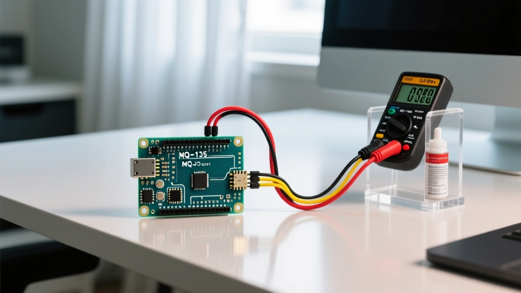

The Reality of Out-of-the-Box Gas Sensors
When you purchase a standard MQ-series gas detector sensor Arduino module online for $2 to $4, you are getting a highly sensitive but fundamentally uncalibrated chemical resistor. The factory testing ensures the sensor functions, but the onboard potentiometer and default analog readings are practically useless for measuring precise Parts Per Million (PPM) of gases like CO2, NH3, or Carbon Monoxide. To transform a basic gas detector sensor Arduino project from a novelty into a reliable environmental monitoring tool, you must perform a rigorous mathematical calibration and account for environmental drift.
In this guide, we will dissect the exact calibration protocols for the ubiquitous MQ-135 (Air Quality) and MQ-7 (Carbon Monoxide) sensors, explore the underlying voltage divider mathematics, and provide actionable strategies to mitigate temperature and humidity interference in 2026.
Hardware Selection: MQ Series vs. Digital Environmental Sensors
Before writing a single line of calibration code, it is critical to understand the hardware limitations of metal-oxide (MOX) sensors compared to modern digital alternatives. While MOX sensors are cheap and sensitive, they lack specificity and require complex calibration.
| Sensor Model | Technology | Target Gases | Typical Price (2026) | Calibration Complexity | Best Use Case |
|---|---|---|---|---|---|
| MQ-135 | MOX (Analog) | NH3, NOx, CO2, VOCs | $2.00 - $4.00 | High (Requires R0 baseline) | General indoor air quality trending |
| MQ-7 | MOX (Analog) | Carbon Monoxide (CO) | $2.50 - $4.50 | High (Requires heater pulsing) | Dedicated CO leak detection |
| Bosch BME680 | MOX + Digital I2C | VOCs, CO2 equiv. | $10.00 - $15.00 | Low (Internal algorithms) | Precise indoor air quality (IAQ) |
| Sensirion SGP40 | MOX + Digital I2C | VOCs, NOx | $8.00 - $12.00 | Low (Self-calibrating) | Smart HVAC integration |
For strict safety applications (e.g., life-safety CO detection), never rely solely on an Arduino and an MQ-7. Always use UL-listed commercial detectors. However, for DIY environmental logging, the MQ series remains a staple due to its raw analog output, provided you calibrate it correctly. For authoritative guidelines on air quality thresholds, refer to the EPA Air Quality Index (AQI) standards.
The Core Mathematics: Calculating Rs and R0
The Arduino does not read gas concentration; it reads voltage. The MQ sensor acts as a variable resistor ($R_s$) whose resistance drops as gas concentration increases. The breakout board pairs this with a fixed load resistor ($R_L$), creating a voltage divider. On 99% of commercial MQ-135 breakout boards, $R_L$ is a 1KΩ (1000 ohm) surface-mount resistor.
Step 1: Calculate Sensor Resistance ($R_s$)
The Arduino's ADC (Analog-to-Digital Converter) reads the voltage across the load resistor ($V_{RL}$). Using the supply voltage ($V_c$, typically 5V on the sensor's VCC pin), we calculate $R_s$ using the voltage divider formula:
Formula: $R_s = R_L imes ((V_c / V_{RL}) - 1)$
Note: In Arduino code, $V_{RL}$ is derived from the analog read value:
V_RL = analogRead(pin) * (5.0 / 1023.0)
Step 2: Determine the Clean Air Baseline ($R_0$)
$R_0$ is the sensor's resistance in perfectly clean air. According to the Hanwei Electronics MQ-135 datasheet, the standard clean air ratio of $R_s / R_0$ is approximately 9.8. Therefore, once you measure $R_s$ in a known clean environment, you divide that value by 9.8 to establish your $R_0$ baseline.
Step-by-Step Calibration Protocol
To achieve reliable PPM readings, follow this exact burn-in and calibration sequence. Do not skip the pre-heat phase; the tin dioxide ($SnO_2$) sensing layer requires thermal stabilization to burn off factory impurities.
- The 24-Hour Burn-In: Power the sensor continuously for 24 hours in a well-ventilated, clean-air environment. This stabilizes the internal heating element and outgasses manufacturing residues.
- Measure Clean Air $R_s$: After the burn-in, upload a basic sketch to read the analog pin 100 times, average the results, and calculate $R_s$ using the formula above.
- Calculate $R_0$: Divide your averaged $R_s$ by 9.8 (for MQ-135). Hardcode this $R_0$ value into your final production sketch.
- PPM Calculation: Use the logarithmic regression formula provided in the datasheet: $PPM = a imes (R_s / R_0)^b$. The constants $a$ and $b$ vary by gas type and must be extracted from the datasheet's logarithmic sensitivity charts.
Pro-Tip: Instead of doing this math manually, utilize the widely adopted MQUnifiedsensor library in the Arduino IDE. It automates the $R_s/R_0$ calculations and includes pre-configured regression constants for CO2, NH3, and CO.
Environmental Drift: Temperature and Humidity Compensation
The single largest source of inaccuracy in a gas detector sensor Arduino build is environmental drift. MOX sensors are highly susceptible to ambient temperature and relative humidity (RH). If your room temperature drops from 25°C to 15°C, the sensor's baseline resistance will shift, triggering false high-gas alarms.
Implementing Software Compensation
To counteract this, you must pair your MQ sensor with a dedicated temperature/humidity sensor like the DHT22 or SHT31. The compensation algorithm applies a correction factor to your calculated $R_s$ before deriving the PPM.
- Temperature Correction: If the ambient temperature is below 20°C, the sensor sensitivity decreases. You must multiply your $R_s$ reading by a temperature correction factor (typically found in the datasheet's temp-dependency graph, often around 1.1 to 1.3 for cold environments).
- Humidity Correction: High humidity (>60% RH) causes water molecules to compete with gas molecules on the sensor surface, artificially lowering resistance. Apply a negative compensation factor when RH exceeds 65%.
Real-World Failure Modes and Edge Cases
Even with perfect math, hardware realities can ruin your data. Watch out for these specific failure modes:
1. The 3.3V Logic Trap
Many makers connect MQ sensors to 3.3V microcontrollers (like the ESP32 or Arduino Due). Do not do this without a proper circuit. MQ sensors require 5V on the VCC pin to heat the internal resistor adequately. If you power it with 3.3V, the sensor will never reach its operating temperature (~300°C), resulting in wildly inaccurate, low-sensitivity readings. Furthermore, the analog out pin will output up to 5V, which can fry a 3.3V ADC pin. Use a bidirectional logic level shifter or a simple voltage divider on the analog out line.
2. Sensor Poisoning
Exposing MQ sensors to high concentrations of silicone vapors, lead, or sulfur compounds will permanently 'poison' the catalytic surface. Once poisoned, the sensor will lose its sensitivity to target gases and cannot be recalibrated. Keep these sensors away from silicone-based thermal pastes or 3D printing enclosures that off-gas volatile silicones.
3. Saturation and Recovery Time
If exposed to a massive spike in gas (e.g., holding a lighter near the MQ-135), the sensor will saturate. The recovery time to return to baseline $R_0$ can take anywhere from 30 minutes to several hours in fresh air. Do not attempt to recalibrate or measure baseline resistance immediately after a saturation event.
Conclusion
Building an accurate gas detector sensor Arduino project requires moving beyond simple analog reads. By respecting the 24-hour burn-in period, rigorously calculating your specific $R_0$ baseline, and implementing environmental compensation, you can extract highly reliable PPM data from inexpensive MOX hardware. For projects demanding absolute precision without the mathematical overhead, upgrading to digital I2C alternatives like the Bosch BME680 is highly recommended for modern 2026 builds.