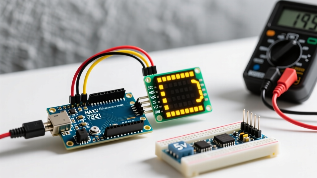

Introduction to MAX7219 Dot Matrix Integration
Interfacing an arduino with led display hardware is a foundational skill in embedded systems, and the MAX7219 8x8 dot matrix module remains the undisputed champion for low-cost, high-visibility output. Whether you are building a scrolling stock ticker, a digital clock, or a retro gaming console, the generic FC-113 4-in-1 MAX7219 module offers 256 individually addressable LEDs for roughly $5.50 in 2026.
However, simply plugging jumper wires into a breadboard often leads to flickering, microcontroller resets, and 'ghosting' artifacts. This comprehensive wiring and code guide bypasses the generic tutorials and dives deep into the electrical realities of SPI communication, current sinking, and hardware-level troubleshooting for the MAX7219.
The Hidden Trap: Power Calculations and Thermal Limits
The most common failure mode when wiring an Arduino with LED display matrices is underestimating the current draw. The MAX7219 chip is a constant-current sink driver. According to the Analog Devices MAX7219 datasheet, the chip can sink up to 320mA per digit (matrix) at maximum intensity.
CRITICAL WARNING: A standard 4-in-1 MAX7219 module contains four matrices. At intensity level 15 (maximum), the theoretical peak current draw is 1.28 Amps (4 x 320mA).
Why Your Arduino Nano Keeps Resetting
Most clone Arduino Nano V3.0 boards utilize the AMS1117-5.0 linear voltage regulator. This regulator has a maximum output current of 800mA, but practically, it will trigger thermal shutdown around 500mA to 600mA when powered via the VIN pin. If you wire the VCC of a 4-in-1 LED display directly to the Nano's 5V pin and crank up the brightness, the voltage regulator will overheat, drop the voltage below 4.5V, and cause the ATmega328P microcontroller to brown-out and reset continuously.
The 2026 Power Injection Solution
- Low Brightness (Intensity 1-4): Safe to power via the Arduino's 5V pin if using a high-quality USB-C cable connected to a 2.4A wall adapter. Average draw stays under 350mA.
- High Brightness (Intensity 5-15): You must bypass the Arduino's onboard regulator. Use an LM2596 5V step-down buck converter wired directly to your main power supply, sharing a common ground (GND) with the Arduino Nano.
Hardware SPI vs. Software SPI: Pinout Guide
While libraries allow you to bit-bang the MAX7219 using any digital pins (Software SPI), this blocks the main execution loop and causes choppy animations. For smooth scrolling text, you must use the Arduino's dedicated Hardware SPI bus. As outlined in the official Arduino SPI communication guide, hardware SPI offloads the clock timing to the microcontroller's dedicated shift registers.
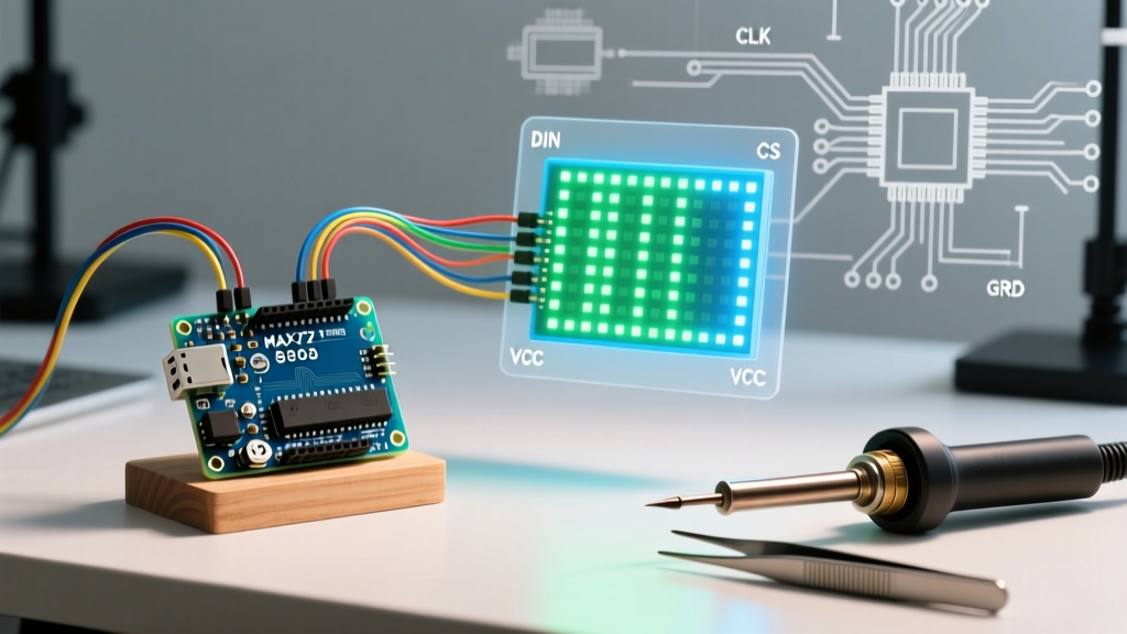
| MAX7219 Module Pin | Arduino Nano / Uno Pin | Function & Notes |
|---|---|---|
| VCC | 5V (or External 5V) | Requires 5V. Do NOT use 3.3V. |
| GND | GND | Must share common ground with external PSU. |
| DIN (Data In) | D11 (MOSI) | Hardware SPI Master Out Slave In. |
| CS (Chip Select) | D10 (SS) | Active LOW. Pulls display attention to data. |
| CLK (Clock) | D13 (SCK) | Hardware SPI Clock. Do not use D12 (MISO). |
Daisy-Chaining Edge Cases
When wiring multiple 4-in-1 modules together (up to 8 modules / 32 matrices), connect the DOUT of the first module to the DIN of the second. Pro-Tip: The thin copper traces on generic FC-113 PCBs suffer from severe voltage drop over long chains. If your last module flickers, solder a thick 22AWG wire directly from your 5V power supply to the VCC and GND pins of the last module in the chain to inject power at the end of the line.
Library Selection: MD_MAX72XX vs. LedControl
To drive the display, you need a robust library. The legacy LedControl library is frequently recommended in outdated forums, but it lacks hardware SPI support and advanced animation buffers.
- LedControl: Good for static numbers and basic 8x8 sprites. Uses software SPI (slow). Max 8 matrices.
- MD_MAX72XX & MD_Parola: The industry standard for 2026. Developed by MajicDesigns, this library utilizes hardware SPI, supports up to 255 matrices, and includes built-in scrolling, sprite animation, and double-height text buffers. Check the MD_MAX72XX GitHub repository for the latest source code.
Writing the Code: Hardware SPI Scrolling Text
Below is a production-ready C++ sketch using the MD_Parola and MD_MAX72XX libraries to scroll text across a 4-in-1 module using Hardware SPI. Install both libraries via the Arduino Library Manager before compiling.
#include <MD_Parola.h>
#include <MD_MAX72xx.h>
#include <SPI.h>

// Define hardware type and pinout
#define HARDWARE_TYPE MD_MAX72XX::FC16_HW
#define MAX_DEVICES 4
#define CS_PIN 10

// Initialize Hardware SPI object
MD_Parola P = MD_Parola(HARDWARE_TYPE, CS_PIN, MAX_DEVICES);

void setup() {
  P.begin();
  P.setIntensity(5); // 0-15. Keep under 8 if powered via Arduino 5V pin.
  P.displayText("Electrical Flux 2026", PA_CENTER, 50, 1000, PA_SCROLL_LEFT, PA_SCROLL_LEFT);
}

void loop() {
  if (P.displayAnimate()) {
    P.displayReset();
  }
}
Code Breakdown & Hardware Types
Notice the HARDWARE_TYPE definition. Generic modules usually fall into three physical wiring categories: FC16_HW (most common for 4-in-1 boards), GENERIC_HW, and PAROLA_HW. If your scrolling text appears as mirrored gibberish or upside down, change the hardware type constant and re-upload. The PA_SCROLL_LEFT parameter dictates the animation entry and exit styles, which the Parola library handles in the background via timer interrupts, keeping your main loop() free for sensor readings.
Advanced Troubleshooting & Failure Modes
Even with correct wiring, environmental and electrical factors can disrupt your display. Use this diagnostic matrix to resolve anomalies:
1. Random 'Garbage' Characters Appearing
Cause: SPI clock speed mismatch or electromagnetic interference (EMI) on long jumper wires.
Fix: Keep DIN, CLK, and CS jumper wires under 15cm. If longer runs are required, use a logic level shifter or an SPI bus extender IC like the PCA9615. Ensure your breadboard contacts are tight; loose Dupont wires cause micro-disconnects that corrupt the 16-bit SPI shift register.
2. 'Ghosting' or Faint Shadows on Adjacent Matrices
Cause: Ground bounce. The multiplexing nature of the MAX7219 switches rows at 800Hz. High current switching on thin, shared ground traces causes a temporary voltage spike, faintly lighting up adjacent LEDs.
Fix: Solder a bypass capacitor (100µF electrolytic) across the VCC and GND pins of the module, and reinforce the ground plane with a thick copper wire soldered across all GND header pins.
3. Display Freezes After 10 Minutes of Operation
Cause: Thermal throttling of the Arduino's voltage regulator or the MAX7219 chip itself. The MAX7219 dissipates excess voltage as heat.
Fix: Lower the P.setIntensity() value to 3 or 4. In indoor environments, an intensity of 4 is remarkably bright and reduces power consumption and heat generation by over 60%, ensuring stable long-term operation.
Final Integration Thoughts
Successfully wiring an Arduino with LED display matrices requires respecting the physics of current draw and the strict timing of the SPI protocol. By utilizing Hardware SPI via the MD_MAX72XX library, injecting adequate 5V current, and reinforcing ground paths, you transform a flickering prototype into a robust, commercial-grade display peripheral ready for 24/7 operation.