
The Flaw in Standard Micro Servo Arduino Tutorials
If you have ever built a basic micro servo Arduino project using an HC-SR04 ultrasonic sensor and a TowerPro SG90, you likely encountered two major issues: acoustic noise interference and severe PWM jitter. Standard tutorials often wire the servo directly to the Arduino 5V pin and rely on the Servo.h library while simultaneously polling an ultrasonic sensor using delay() or blocking interrupts. This architecture guarantees micro-stutters in the servo arm and frequent ATmega328P brownout resets due to current spikes.
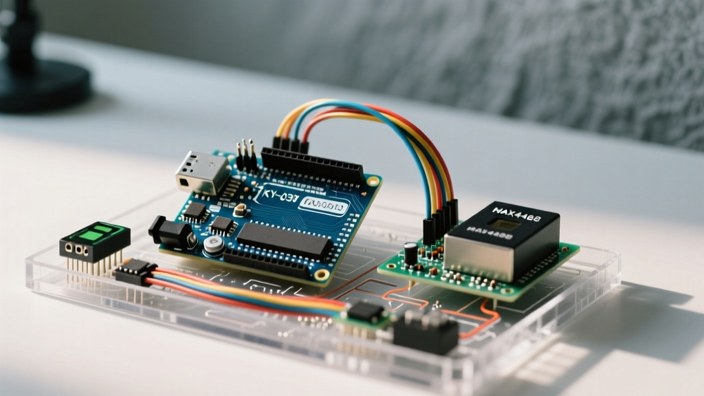
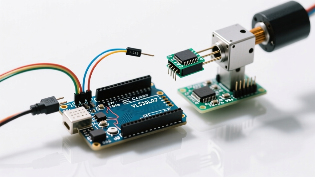
In this advanced sensor integration tutorial, we completely overhaul the traditional setup. We will interface a metal-geared micro servo with an Arduino using a VL53L0X Time-of-Flight (ToF) laser sensor and a dedicated PCA9685 hardware PWM driver. This approach eliminates software-based PWM jitter, isolates high-current actuator loads, and leverages photon-based distance measurement for sub-millimeter precision in automated valves, camera gimbals, and robotic end-effectors.
2026 Precision Bill of Materials
As of early 2026, supply chain stabilization has brought the cost of advanced I2C sensors and metal-gear micro servos down significantly. We are moving away from the plastic-gear SG90 to the MG90S for durability, and utilizing a 3.3V native microcontroller to bypass the need for bi-directional logic level shifters on the I2C bus.
| Component | Model / Specification | Role | Est. Cost |
|---|---|---|---|
| Microcontroller | Arduino Nano 33 IoT (SAMD21) | Native 3.3V logic, I2C master | $18.50 |
| Micro Servo | TowerPro MG90S (Metal Gear) | Actuator (2.2 kg-cm torque) | $5.50 |
| Distance Sensor | VL53L0X ToF Breakout | 940nm VCSEL laser ranging | $7.00 |
| PWM Driver | PCA9685 16-Channel Module | Hardware I2C PWM generation | $3.50 |
| Power Supply | LM2596 Buck Converter | Step-down to 5.0V for servo | $2.00 |
Hardware Architecture: Eliminating Brownouts and Jitter
Power Isolation Strategy
The most common failure mode in micro servo Arduino builds is the USB brownout. The MG90S micro servo draws approximately 10mA at idle but can spike to 650mA during stall or rapid acceleration. The Arduino Nano's onboard 5V regulator or USB polyfuse is typically rated for only 300mA to 500mA. When the servo demands peak current, the voltage on the 5V rail sags below the microcontroller's brownout detection threshold (usually 4.3V), causing the MCU to reset and the servo to twitch violently.
The Fix: Use an external LM2596 buck converter module. Set the potentiometer on the buck converter to output exactly 5.05V under load. Wire the VIN and GND of the MG90S directly to the buck converter, and connect the GND of the buck converter to the GND of the Arduino Nano 33 IoT to establish a common ground reference. Do not route the servo's power through the breadboard's thin power rails, as they introduce resistance and voltage drop.
Native 3.3V I2C Routing
The VL53L0X ToF sensor and the PCA9685 PWM driver both communicate via I2C and operate natively at 3.3V logic. If you use a standard 5V Arduino Uno, you must use a logic level shifter (like the BSS138) to prevent frying the sensor's SDA/SCL pins over time. By selecting the Arduino Nano 33 IoT, the SAMD21 Cortex-M0+ processor operates at 3.3V natively. This allows you to wire the I2C bus directly, reducing bus capacitance and eliminating the clock-stretching timeouts often caused by cheap MOSFET-based level shifters. For deeper insights on I2C electrical characteristics, refer to the Arduino I2C Reference.
Wiring Matrix & Pinout
Proper I2C pull-up resistors are critical. The PCA9685 breakout usually includes 10kΩ pull-ups, but the VL53L0X may require additional 4.7kΩ pull-ups on the SDA and SCL lines if the cable length exceeds 15cm.
| Source Pin | Destination Pin | Wire Color (Std) | Notes |
|---|---|---|---|
| Nano 33 IoT 3.3V | VL53L0X VIN & PCA9685 VCC | Red | Logic power only |
| Nano 33 IoT GND | Common Ground Bus | Black | Must share GND with 5V buck |
| Nano 33 IoT SDA | VL53L0X SDA & PCA9685 SDA | Blue | I2C Data Line |
| Nano 33 IoT SCL | VL53L0X SCL & PCA9685 SCL | Yellow | I2C Clock Line |
| Buck Converter 5V | MG90S Red Wire & PCA9685 V+ | Orange | High current servo power |
| PCA9685 Ch 0 | MG90S Signal (Orange/White) | Green | Hardware PWM signal |
Firmware: Non-Blocking ToF Mapping with Moving Average
To prevent the servo from jittering due to photon shot noise (a natural variance in ToF laser returns), we implement a 10-sample moving average filter. Furthermore, we use the Adafruit_PWMServoDriver library to offload PWM generation to the PCA9685 hardware, freeing the MCU to handle I2C sensor polling without interrupting the servo signal.
#include <Wire.h>
#include <Adafruit_VL53L0X.h>
#include <Adafruit_PWMServoDriver.h>

Adafruit_VL53L0X lox = Adafruit_VL53L0X();
Adafruit_PWMServoDriver pwm = Adafruit_PWMServoDriver();

const int SERVOMIN = 150; // Min pulse length out of 4096
const int SERVOMAX = 600; // Max pulse length out of 4096
const int CHANNEL = 0;

float distanceBuffer[10];
int bufferIndex = 0;
unsigned long lastRead = 0;

void setup() {
  Serial.begin(115200);
  Wire.begin();

  pwm.begin();
  pwm.setOscillatorFrequency(27000000);
  pwm.setPWMFreq(50); // Standard 50Hz for analog servos

  if(!lox.begin()) {
    Serial.println(F('Failed to boot VL53L0X'));
    while(1);
  }
}

void loop() {
  if(millis() - lastRead >= 50) { // Poll every 50ms
    lastRead = millis();
    VL53L0X_RangingMeasurementData_t measure;
    lox.rangingTest(&measure, false);

    if (measure.RangeStatus != 4) { // 4 indicates out of range
      distanceBuffer[bufferIndex] = measure.RangeMilliMeter;
      bufferIndex = (bufferIndex + 1) % 10;

      float avgDist = 0;
      for(int i=0; i<10; i++) avgDist += distanceBuffer[i];
      avgDist /= 10.0;

      // Map 50mm - 500mm to servo pulse width
      avgDist = constrain(avgDist, 50, 500);
      int pulseLen = map(avgDist, 50, 500, SERVOMIN, SERVOMAX);
      pwm.setPWM(CHANNEL, 0, pulseLen);
    }
  }
}
For comprehensive wiring and initialization details regarding the ToF sensor, the Adafruit VL53L0X Guide provides excellent baseline schematics.
Mechanical Edge Cases and Failure Modes
When integrating a micro servo Arduino system into a physical enclosure, software limits are just as important as electrical isolation. Here are the critical edge cases you must design around:
- Hard-Stop Gear Stripping: The MG90S has a mechanical hard stop near 0° and 180°. If your code commands a pulse width that pushes the servo against this physical wall, the motor will stall, draw 650mA continuously, and eventually strip the first metal gear or overheat the internal H-bridge. Solution: Software-limit your mapping range to roughly 15° through 165° to provide a mechanical buffer.
- I2C Bus Lockup: In high-noise environments (near brushless motors or switching power supplies), the VL53L0X can occasionally pull the SDA line low and freeze the I2C bus. Solution: Implement a hardware watchdog timer (WDT) on the SAMD21, or write a software I2C bus recovery routine that toggles the SCL pin manually to release the stuck sensor.
- VCSEL Ambient Light Saturation: While the 940nm VCSEL laser is highly immune to indoor lighting, direct sunlight contains massive amounts of infrared radiation. If your sensor faces a window, the ambient IR can blind the SPAD (Single-Photon Avalanche Diode) array, returning a RangeStatus of 4 (Out of Bounds). Solution: Use the
setMeasurementTimingBudgetMicroSeconds()function to increase the timing budget to 200ms for outdoor/high-IR environments, trading update speed for dynamic range.
Expert Tip: Never rely on the internal potentiometer of a micro servo for absolute positional feedback. The carbon tracks inside the MG90S wear out over thousands of cycles, leading to a 'dead band' in the center position. If your application requires closed-loop precision, upgrade to a digital feedback servo or add an external AS5600 magnetic rotary encoder to the pivot joint.
By abandoning the flawed direct-drive, 5V-logic paradigm and adopting native 3.3V I2C routing with hardware PWM offloading, your micro servo Arduino projects will achieve industrial-grade reliability. For further reading on micro servo torque curves and stall specifications, review the SparkFun Micro Servo Specs documentation to ensure your mechanical load never exceeds 60% of the rated 2.2 kg-cm limit for continuous operational lifespan.