
The Pin-Count Dilemma in Multi-Peripheral Projects
When designing complex embedded systems, integrating an arduino 7 segment display often creates an immediate I/O bottleneck. A standard single-digit 7-segment display requires 8 digital pins (7 for the segments plus 1 for the decimal point). A 4-digit display wired directly demands a staggering 12 pins when accounting for the common cathode/anode multiplexing lines. In a multi-peripheral setup—where you might already be routing an HC-SR04 ultrasonic sensor (2 pins), a DHT22 temperature sensor (1 pin), an I2C OLED (2 pins), and a 2-channel relay module (2 pins)—the ATmega328P's 14 available digital I/O pins are rapidly exhausted.
To successfully integrate visual numeric feedback without starving your sensor array of necessary connections, you must decouple the display from direct GPIO control. This guide explores the three most effective architectural patterns for driving 7-segment displays in dense peripheral environments, analyzing I2C bus loading, shift register timing, and interrupt-driven multiplexing.
Architecture Comparison: Direct vs. I2C vs. Shift Registers
Choosing the right interface depends entirely on your existing peripheral bus topology. Below is a decision matrix for 2026 multi-sensor projects.
| Interface Method | Pins Required | Approx. Cost (2026) | Bus/Resource Impact | Best Use Case |
|---|---|---|---|---|
| Direct GPIO Wiring | 8 to 12 | $1.50 (Bare Display) | High (Exhausts DIO) | Single-sensor, simple projects |
| HT16K33 I2C Backpack | 2 (SDA/SCL) | $9.50 - $11.00 | Medium (Adds I2C Load) | Setups with free I2C addresses |
| 74HC595 Shift Register | 3 (Data, Clock, Latch) | $0.45 - $0.80 | Low (Uses generic DIO) | I2C-saturated buses, high EMI |
| TM1637 Proprietary | 2 (CLK, DIO) | $1.20 - $2.00 | Low (Custom Protocol) | Budget multi-sensor dashboards |
Strategy 1: The HT16K33 I2C Backpack (Offloading to Hardware RAM)
The Holtek HT16K33 driver chip is the gold standard for I2C-based 7-segment integration. Modules like the Adafruit 1.2" 4-Digit 7-Segment Display w/I2C Backpack (Product ID: 1270) feature onboard display RAM. This is critical for multi-peripheral setups: the microcontroller only needs to send I2C bytes when the numeric value changes, completely freeing the MCU to poll sensors without worrying about display refresh rates.
I2C Address Conflicts and Bus Capacitance
The default I2C address for the HT16K33 is 0x70. In dense setups, this can collide with other peripherals. For instance, if you are using a PCA9685 PWM driver for servos, its address space overlaps. Fortunately, the HT16K33 breakout boards include three address jumper pads (A0, A1, A2), allowing you to shift the address up to 0x77.
Expert Warning: Every I2C device adds roughly 10pF to 15pF of capacitance to the bus. The I2C specification limits bus capacitance to 400pF. If your multi-peripheral setup includes long wire runs, an OLED, a BME680, and an HT16K33, you may experience data corruption. Always verify your bus with an oscilloscope and consider adding 2.2kΩ pull-up resistors (instead of the standard 4.7kΩ) to sharpen the signal rise times.
Strategy 2: The 74HC595 Shift Register (Bypassing I2C Congestion)
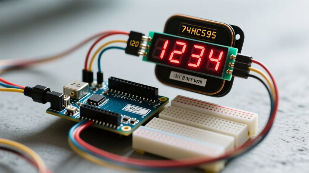
If your I2C bus is already saturated, or if you are operating in a high-EMI environment (such as near inductive loads or AC relays) where I2C packet corruption is common, the Texas Instruments SN74HC595N shift register is the superior choice. By utilizing the Arduino shiftOut() function, you can control an entire 4-digit display using just three digital pins: SER (Serial Data), SRCLK (Shift Register Clock), and RCLK (Storage Register Clock).
Wiring and Decoupling for Stability
When chaining shift registers for multi-digit displays, power integrity is paramount. A 4-digit display drawing 20mA per segment can pull upwards of 150mA instantaneously when multiple digits illuminate.
- Decoupling: Place a 100nF ceramic capacitor directly across the VCC and GND pins of every 74HC595 IC. Do not rely on the breadboard's power rail capacitance.
- Current Limiting: Use a 220Ω resistor for each segment line. If you are multiplexing the common cathodes via NPN transistors (like the BC337), ensure you include a 1kΩ base resistor to prevent GPIO overcurrent.
- Ghosting Prevention: When shifting data to the next digit, the previous digit's segments may briefly illuminate if the latch pin is toggled before the common cathode is switched off. Always turn off the common cathode, shift the new data, latch, and then turn the new cathode on.
The Timing Trap: Sensor Blocking vs. Display Multiplexing
The most common failure mode in multi-peripheral Arduino projects involving bare 7-segment displays is flickering caused by sensor polling. Sensors like the DHT22 require the MCU to disable interrupts and block execution for up to 25 milliseconds to read the 40-bit data stream. If your 7-segment display relies on software-based millis() multiplexing, this 25ms blocking window will cause the active digit to remain on too long, resulting in severe flickering, uneven brightness, and in extreme cases, thermal damage to the LED die.
The Hardware Interrupt Solution
To resolve this without abandoning bare multiplexing, you must offload the display refresh to a hardware timer. Using the TimerOne library, you can configure Timer1 to trigger an interrupt service routine (ISR) every 2 milliseconds. The ISR handles the cathode switching and segment latching in the background. Because hardware timers operate independently of the main loop, the display remains perfectly stable even when the main thread is blocked waiting for an ultrasonic sensor echo or a DHT22 handshake.
2026 Hardware Bill of Materials (BOM) & Pricing
When budgeting for your multi-sensor dashboard, consider the hidden costs of supporting components. Below is a realistic BOM for a robust shift-register-based 4-digit display setup.
- Generic 4-Digit 7-Segment Display (Common Cathode, 0.56"): $1.20
- SN74HC595N DIP-16 ICs (x2): $0.90
- BC337 NPN Transistors (x4 for digit multiplexing): $0.40
- Resistor Assortment (220Ω for segments, 1kΩ for bases): $0.15
- 100nF MLCC Decoupling Capacitors (x2): $0.10
- Total Estimated Component Cost: ~$2.75 (excluding PCB and wiring)
Compare this to the $11.00 cost of a pre-assembled I2C backpack module. The shift register approach requires more soldering and complex firmware, but saves nearly $8.00 per unit in production and entirely avoids I2C address conflicts.
Troubleshooting Edge Cases in Dense Setups
Even with perfect wiring, multi-peripheral environments introduce unique electrical anomalies. Here is how to diagnose the most frequent 7-segment issues:
- Dimming During Relay Switching: If your display dims momentarily when a relay module clicks, the relay's inductive kickback is starving the 5V rail. Fix: Isolate the relay module's VCC/JDVcc jumper and power the relay coil from a separate 5V buck converter, sharing only the ground reference with the Arduino.
- Random Segments Illuminating (Noise): Long unshielded wires acting as antennas can pick up EMI from nearby switching power supplies, triggering the shift register's clock pin. Fix: Add a 10kΩ pull-down resistor on the SRCLK and RCLK lines to keep them in a known LOW state when the MCU pin is floating or transitioning.
- I2C Bus Lockups: If the HT16K33 freezes and requires a hard reset, a voltage spike on the SDA/SCL lines may have corrupted the I2C state machine. Fix: Implement a software I2C watchdog in your code that detects bus timeouts and manually toggles the SCL pin 9 times to release any stuck slave devices.
Further Reading and Authoritative References
For deeper schematic analysis and datasheet specifications, consult the following engineering resources:
- Arduino Official Reference: shiftOut() Function - Detailed timing diagrams for serial-to-parallel data shifting.
- Texas Instruments SN74HC595 Datasheet - Essential reading for understanding maximum current sourcing limits and propagation delays.
- Adafruit Learning System: LED Backpacks - Comprehensive guide on I2C address mapping and HT16K33 RAM registers.