
Decoding the Datasheet: 4 Digit Seven Segment Display Arduino Integration
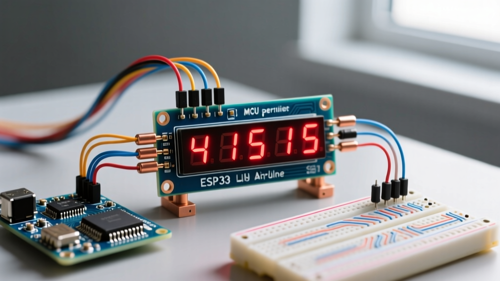
When integrating a 4 digit seven segment display Arduino project, many makers skip the datasheet and jump straight to copying code. This often results in flickering numbers, 'ghosting' segments, or worse, a fried microcontroller pin. Bare 4-digit displays—like the ubiquitous 5641AH (common cathode) or 3461BS (common anode)—are deceptively simple components that require a solid grasp of multiplexing and current limiting to function correctly.
In this datasheet explainer, we break down the technical specifications, electrical characteristics, and timing requirements hidden in the manufacturer PDFs. Whether you are building a digital clock, a temperature monitor, or a scoreboard, understanding these parameters is the difference between a reliable build and a frustrating failure. As of 2026, bare 5641AH displays remain a budget-friendly staple, typically costing between $0.60 and $0.90, but they demand precise electrical management compared to plug-and-play I2C backpacks.
The 12-Pin Matrix: Mapping the Internal Wiring
A standard 4-digit seven segment display features 12 physical pins. If you look at the datasheet's internal schematic, you will see that it does not contain 28 individual LEDs (7 segments × 4 digits). Instead, it uses a matrix configuration to save pins. All 'A' segments across the four digits are tied together, all 'B' segments are tied together, and so on. The common pins (either cathode or anode) are what isolate the digits.
Standard Pinout Configuration (Top View)
Below is the universal pin mapping for most 12-pin 4-digit displays. Always verify with your specific component's datasheet, as some manufacturers swap the digit pins.
| Pin Number | Function | Description |
|---|---|---|
| 1 | e | Segment E (Bottom Left) |
| 2 | d | Segment D (Bottom) |
| 3 | D1 | Digit 1 Common Pin (Rightmost) |
| 4 | D2 | Digit 2 Common Pin |
| 5 | DP | Decimal Point |
| 6 | c | Segment C (Bottom Right) |
| 7 | g | Segment G (Middle) |
| 8 | D3 | Digit 3 Common Pin |
| 9 | D4 | Digit 4 Common Pin (Leftmost) |
| 10 | b | Segment B (Top Right) |
| 11 | a | Segment A (Top) |
| 12 | f | Segment F (Top Left) |
According to SparkFun's Seven Segment Display Tutorial, identifying whether your display is Common Anode (CA) or Common Cathode (CC) is the critical first step. A 5641AH is CC (requires HIGH on segments, LOW on digits), while a 3461BS is CA (requires LOW on segments, HIGH on digits).
Electrical Characteristics: Why Current Limiting is Non-Negotiable
The most frequently ignored section of the datasheet is the Absolute Maximum Ratings. A standard red 4-digit display has a Forward Voltage ($V_f$) of roughly 2.0V to 2.2V per segment, and a maximum Continuous Forward Current ($I_f$) of 20mA per segment. The common digit pin, which sinks or sources current for up to 8 segments simultaneously, usually has a maximum rating of 80mA to 100mA.
Calculating the Resistor Values
If you connect a 5V Arduino GPIO pin directly to a segment pin without a resistor, the LED will attempt to draw as much current as the power supply can provide. This will instantly exceed the 20mA limit, destroying the LED junction or the Arduino's ATmega328P microcontroller pin (which has a strict 20mA absolute max per I/O pin).
Use Ohm's Law to calculate the required current-limiting resistor for each of the 8 segment pins (a-g and dp):
Formula: R = (V_source - V_f) / I_target
For Red Display (5V Arduino): R = (5.0V - 2.0V) / 0.015A = 200Ω
Standard Value: Use 220Ω resistors.
Note: For blue or green displays (like the 3461BS), the $V_f$ is higher (typically 3.2V). The calculation becomes R = (5.0V - 3.2V) / 0.015A = 120Ω. Always use the next highest standard resistor value to ensure longevity.
The Multiplexing Secret: Persistence of Vision
Datasheets for these displays do not explicitly explain how to drive them with a microcontroller; they only provide the electrical limits. Because the segments are shared, you cannot display '1234' all at once. You must use a technique called multiplexing, relying on the human eye's persistence of vision. For a deeper dive into the physics of this, the All About Circuits Multiplexing Guide provides excellent foundational theory.
Timing the Refresh Rate
To display a 4-digit number, your Arduino must cycle through the digits sequentially:
- Activate Digit 1 (pull common pin LOW for CC).
- Set segment pins for the first number.
- Wait for a brief interval (e.g., 2 milliseconds).
- Deactivate Digit 1 (turn off all segments to prevent ghosting).
- Repeat for Digits 2, 3, and 4.
If each digit is lit for 2ms, a full cycle of 4 digits takes 8ms. This results in a refresh rate of 125Hz (1000ms / 8ms). Since the human flicker fusion threshold is around 60Hz, 125Hz appears as a solid, continuous image. If your code includes blocking delays (like delay(100) for sensor reading), the display will freeze or flicker. You must use non-blocking timing, such as millis() or hardware timers, to maintain the multiplexing loop.
Troubleshooting Edge Cases and Failure Modes
Even with correct wiring, raw GPIO multiplexing introduces specific edge cases that datasheets warn about implicitly through timing parameters.
- Ghosting (Bleeding): If you switch the digit pin before turning off the segment pins, the previous number will briefly flash on the new digit. Fix: Always implement a 'blanking' phase. Turn off all segment pins, switch the digit pin, wait 10 microseconds, then apply the new segment data.
- Arduino Brown-Out Resets: If you omit resistors and light up all 8 segments on a single digit, the display will draw 160mA+. This exceeds the USB port's safe threshold and triggers the Arduino's brown-out detection, causing it to reset continuously. Fix: Never skip the 220Ω resistors.
- Uneven Brightness: If your code spends more time calculating sensor data between digit 4 and digit 1, digit 1 will appear dimmer. Fix: Use a hardware timer interrupt (like Timer1 on the ATmega328P) to handle the multiplexing in the background, ensuring mathematically perfect timing regardless of the main loop's workload.
Raw GPIO vs. Dedicated Driver ICs: A 2026 Perspective
While driving a 4 digit seven segment display via raw Arduino GPIO is an excellent learning exercise, it consumes 12 I/O pins and requires constant CPU cycles. In modern 2026 DIY projects, dedicated driver ICs are often the superior choice for reliability. Below is a comparison matrix to help you decide.
| Feature | Raw Arduino GPIO | TM1637 Module | MAX7219 Module |
|---|---|---|---|
| I/O Pins Used | 12 Pins | 2 Pins (CLK, DIO) | 3 Pins (DIN, CLK, CS) |
| CPU Overhead | High (Requires constant loop) | Near Zero (Internal RAM) | Near Zero (Internal RAM) |
| Current Limiting | Requires 8x External Resistors | Built-in (Software adjustable) | Built-in (1x External Resistor) |
| Avg. Cost (2026) | $0.80 (Display only) | $1.50 (Display + IC) | $3.50 (Display + IC) |
| Best Use Case | Learning, extreme pin-count designs | Clocks, simple sensor readouts | Daisy-chaining, high brightness |
For projects requiring multiple displays, the MAX7219 allows you to daisy-chain up to 8 modules using the same 3 Arduino pins, a feature documented extensively in the Arduino Digital Pins Documentation. However, if you are constrained by budget and board space, and only need one display, mastering the raw GPIO multiplexing detailed in this guide remains a highly valuable skill.
Final Thoughts on Datasheet Literacy
Successfully wiring a 4 digit seven segment display to an Arduino is less about memorizing code and more about respecting the electrical boundaries defined in the component's datasheet. By calculating precise current-limiting resistors, implementing a blanking phase to eliminate ghosting, and maintaining a refresh rate above 100Hz, you transform a fragile matrix of LEDs into a robust, professional-grade display interface.