
The Reality of Liquid Flow Measurement in Microcontrollers
When integrating a flow sensor Arduino setup into a hydroponics system, smart water meter, or automated brewing rig, hobbyists typically default to the cheapest option available. However, as of 2026, the market offers distinct tiers of hall-effect liquid flow meters, and choosing the wrong one can lead to catastrophic impeller failure, inaccurate dosing, or microcontroller lockups due to noisy interrupt lines. Understanding the fluid dynamics, signal conditioning, and mechanical limitations of these sensors is the difference between a weekend prototype and a reliable commercial product.
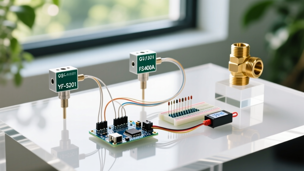
In this component comparison, we are tearing down the three most common hall-effect flow sensors used in the maker and engineering communities: the ubiquitous plastic YF-S201, the compact FS400A, and the industrial-grade brass G1/2" alternatives. We will cover exact K-factor calibration, interrupt-driven code architecture, and the hardware failure modes that datasheets conveniently omit.
Head-to-Head Matrix: YF-S201 vs. FS400A vs. Brass G1/2"
Before diving into the code and wiring, it is critical to match the sensor's mechanical specifications to your plumbing requirements. The following matrix breaks down the physical and electrical characteristics of the top three contenders.
| Specification | YF-S201 (Plastic) | FS400A (Compact) | Sea Sensor G1/2" (Brass) |
|---|---|---|---|
| Thread Size | G1/2" (1/2" BSP) | G1/4" (1/4" BSP) | G1/2" (1/2" BSP) |
| Flow Range | 1 - 30 L/min | 0.3 - 6 L/min | 1 - 30 L/min |
| Max Pressure | 0.8 MPa | 0.8 MPa | 1.75 MPa |
| Body Material | ABS Plastic | ABS Plastic | Forged Brass |
| Nominal K-Factor | F = 4.5 * Q | F = 4.5 * Q | F = 4.5 * Q |
| 2026 Avg Price | $4.50 - $6.00 | $5.00 - $7.50 | $18.00 - $24.00 |
| Best Application | General purpose, low-cost | Micro-dosing, RO systems | High-pressure, hot water |
Deep Dive: The K-Factor Illusion
Almost every datasheet for the YF-S201 and FS400A cites the formula F (Hz) = 4.5 * Q (L/min). This implies that for every liter of water that passes through the sensor per minute, the hall effect sensor outputs 4.5 pulses per second (270 pulses per liter). However, treating this number as an absolute constant is a rookie mistake. Manufacturing tolerances in the injection-molded plastic impellers mean that the actual K-factor can vary by ±10% between batches. For precision dosing, you must empirically calibrate your specific sensor.
Pro-Tip for Empirical Calibration: Do not rely on volumetric jugs. Place a container on a digital kitchen scale (accurate to 1g). Since 1 liter of water at room temperature weighs approximately 998 grams, run your pump until the scale reads exactly 1000g, while your Arduino counts the total interrupts. Divide the total pulse count by 1.002 to get your exact pulses-per-liter constant.
Hardware Integration: Wiring and Signal Conditioning
Hall-effect flow sensors utilize an open-collector NPN transistor output. This means the sensor can pull the signal line to ground (LOW), but it cannot drive it HIGH. You must provide a pull-up resistor. While the Arduino's internal pull-ups (activated via INPUT_PULLUP) seem convenient, they typically range from 20kΩ to 50kΩ. In electrically noisy environments, or when using cables longer than 1 meter, these weak pull-ups result in floating voltages that trigger phantom interrupts, artificially inflating your flow readings.
The Correct Pull-Up and Debouncing Strategy
- External Pull-Up: Use a 4.7kΩ or 10kΩ resistor tied to your microcontroller's logic voltage (5V for Uno R3, 3.3V for ESP32 or Arduino Uno R4).
- Hardware Debouncing: If your cable run exceeds 2 meters, parasitic capacitance will round the edges of your square wave. Pass the signal through a 74HC14 Schmitt trigger hex inverter before it hits the Arduino interrupt pin. This restores sharp, clean edges and prevents multiple interrupt triggers from a single impeller magnet pass.
- Voltage Translation: The YF-S201 is powered by 5V to 18V. If you are using a 3.3V ESP32, power the sensor's red wire with 5V, but use a voltage divider or a logic level shifter on the yellow signal wire to avoid frying the ESP32's GPIO pins.
Code Architecture: The Interrupt Bottleneck
Polling a flow sensor pin inside the loop() function is a guaranteed way to miss pulses, especially at higher flow rates where the YF-S201 can output over 130 Hz. You must use hardware interrupts. According to the official Arduino attachInterrupt() documentation, you should map the pin using the digitalPinToInterrupt() macro to ensure cross-board compatibility.
When writing your Interrupt Service Routine (ISR), keep it as lean as possible. Do not use delay(), do not print to the serial monitor, and do not perform floating-point math inside the ISR. Simply increment a volatile counter.
Example ISR Architecture:
- Declare
volatile unsigned long pulseCount = 0;globally. - Trigger on the
RISINGedge. Triggering onCHANGEwill double your pulse count and is highly susceptible to noise bounce. - In the main
loop(), disable interrupts momentarily usingnoInterrupts(), copy thepulseCountto a local variable, resetpulseCountto zero, and re-enable interrupts withinterrupts(). This atomic operation prevents race conditions where a pulse arrives exactly while the CPU is reading the 32-bit integer.
Real-World Failure Modes and Edge Cases
As detailed in Analog Devices' primer on Hall Effect sensors, magnetic interference and mechanical stress are the primary enemies of these devices. Here are the failure modes you will encounter in the field:
1. Water Hammer and Impeller Shatter
If your system uses fast-acting solenoid valves, closing the valve instantly stops the water column, creating a high-pressure shockwave known as water hammer. In plastic YF-S201 and FS400A sensors, this spike can easily exceed the 0.8 MPa rating, snapping the plastic impeller shaft. Solution: Install a mechanical water hammer arrestor upstream, or use the brass G1/2" sensor which features a metal-reinforced shaft and can withstand pressures up to 1.75 MPa.
2. Cavitation and Air Bubbles
Hall-effect sensors measure the physical rotation of the impeller, not the mass of the fluid. If your pump cavitates or draws in air, the impeller will spin rapidly in the air pocket, registering massive flow rates even though no liquid is moving. Solution: Always mount flow sensors in a vertical pipe section with the flow moving upward, or ensure the sensor is at the lowest point in a horizontal run to prevent air trapping in the sensor cavity.
3. Debris and Bio-Fouling
The gap between the YF-S201 impeller blades and the housing is roughly 1.5mm. A single piece of PTFE tape, a wood shaving from a drilled pipe, or a buildup of hard water scale will jam the rotor. Solution: You must install a 100-micron stainless steel mesh Y-strainer filter immediately upstream of the sensor. In hydroponic applications, algae bio-fouling can coat the internal magnet, weakening the magnetic field until the hall sensor fails to detect the rotation.
4. Magnetic Cross-Talk
Because these sensors rely on detecting a small neodymium magnet embedded in the rotor, placing the sensor within 5 centimeters of a high-current DC motor, a large relay, or another strong magnet will saturate the hall element. This causes the sensor to output a continuous HIGH or LOW signal, completely blinding the microcontroller to flow changes.
Final Verdict: Which Flow Sensor Arduino Setup Wins?
If you are building a low-pressure, cold-water drainage monitor or a basic educational project, the YF-S201 remains the undisputed king of cost-effectiveness at under $6. Its G1/2" thread integrates easily with standard garden hose fittings, and its low flow threshold is adequate for most macro-dosing tasks.
For reverse osmosis (RO) monitoring, coffee machine automation, or precision nutrient dosing where flow rates rarely exceed 5 L/min, the FS400A is vastly superior. Its smaller internal diameter increases fluid velocity at low flow rates, ensuring the impeller spins reliably where the YF-S201 would stall.
However, if your 2026 project involves hot water (up to 80°C), high municipal water pressures, or integration with fast-switching industrial solenoid valves, skip the plastic entirely. The Brass G1/2" Sea Sensor costs roughly four times as much, but its forged body, stainless steel shaft, and superior pressure tolerance will save you weeks of debugging catastrophic mechanical failures in the field.