
The Anatomy of Servo Code Arduino Errors
Integrating servos into DIY robotics, camera gimbals, or automated blinds is a rite of passage for makers. However, executing seemingly perfect servo code Arduino sketches often results in erratic behavior: micro-jitters at idle, stalling under load, or violent oscillations. In 2026, with the market flooded by both high-quality digital servos and ultra-cheap analog clones, isolating the root cause requires a systematic approach. Most troubleshooting guides blame the code, but in reality, 80% of servo anomalies stem from power delivery bottlenecks and signal integrity failures.
This comprehensive diagnostic guide dissects the exact failure modes of popular models like the TowerPro SG90 (micro analog), MG996R (metal gear analog), and the DS3218 (high-torque digital), providing actionable hardware and software fixes.
Diagnostic Matrix: Symptom to Root Cause
Before rewriting your sketch, match your servo's physical behavior to this diagnostic matrix to identify the primary domain of failure.
| Symptom | Probable Root Cause | Domain | Quick Verification Test |
|---|---|---|---|
| Continuous micro-jitter at idle | Power rail noise or missing common ground | Hardware / Wiring | Measure VCC ripple with an oscilloscope; check GND continuity. |
| Stalling or clicking under load | Insufficient stall current supply | Power Supply | Measure voltage drop at servo VCC pins during stall. |
| Servo sweeps randomly on boot | Floating PWM pin during MCU initialization | Software / Wiring | Attach a 10kΩ pull-down resistor to the PWM signal line. |
| Inconsistent end-stop positions | Potentiometer wear or generic pulse-width mapping | Mechanical / Code | Use writeMicroseconds() to manually calibrate limits. |
| Only 1 of 4 servos moves | Timer conflict or I2C address collision | Software | Verify Servo.h timer usage or PCA9685 I2C hex address. |
Power Supply Bottlenecks: The #1 Culprit
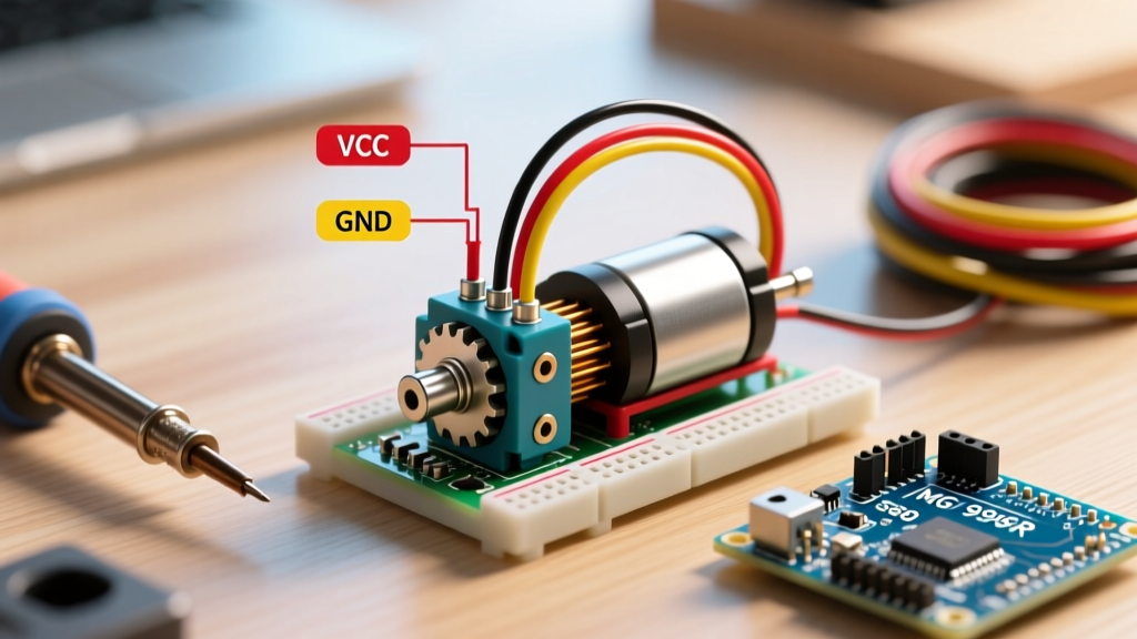
The most common mistake when writing servo code Arduino tutorials is powering the servo directly from the Arduino's 5V pin. This works for a single, unloaded SG90 (stall current ~700mA) but fails catastrophically with larger models.
Understanding Stall Current vs. Operating Current
A servo draws minimal current (10-50mA) when idle or moving freely. However, when it hits a mechanical limit or pushes a load, it stalls. During a stall, the motor acts as a dead short, drawing massive current:
- TowerPro SG90 (9g): ~700mA stall current at 5V.
- TowerPro MG996R (Metal Gear): ~2.5A stall current at 6V.
- DS3218 (20kg High Torque): ~3.5A stall current at 6.8V.
The Arduino Uno's onboard 5V linear regulator (typically an NCP1117) can safely supply only about 800mA when powered via the barrel jack, and it lacks adequate heatsinking. If your MG996R stalls, it will pull 2.5A, instantly tripping the Arduino's polyfuse, causing a brownout reset, or permanently frying the onboard voltage regulator.
The Fix: Dedicated BEC and Capacitor Sizing
Never share the logic power rail with high-torque servo power. Use a dedicated Battery Eliminator Circuit (BEC) or a high-current step-down buck converter (like the LM2596-based modules, costing around $3-$5 in 2026) to supply 5V-6V directly to the servo's red wire.
Expert Pro-Tip: To eliminate transient voltage dips that cause logic brownouts, solder a 1000µF electrolytic capacitor (rated for 10V or higher) directly across the VCC and GND rails of your external servo power bus. For digital servos like the DS3218, add a 0.1µF ceramic capacitor in parallel to filter high-frequency EMI noise generated by the internal PWM driver.
Signal Integrity and Ground Loops
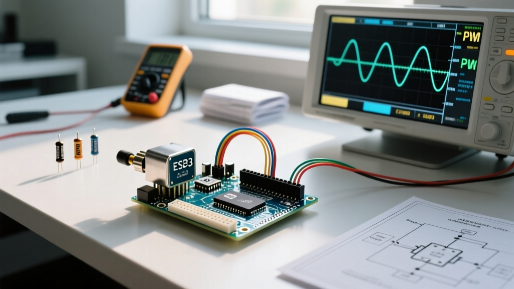
Servos interpret position based on PWM pulse widths, typically ranging from 500µs to 2500µs, repeated every 20ms (50Hz). Because these pulses are measured in microseconds, electrical noise can easily be misinterpreted by the servo's internal comparator as a command to move.
The Shared Ground Imperative
A frequent wiring error is powering the servo from an external battery pack while sending the PWM signal from the Arduino, but failing to connect the grounds. The PWM signal requires a common reference voltage. Without a shared GND wire connecting the Arduino GND to the external battery GND, the signal will float, resulting in violent, unpredictable servo sweeping. Always run a dedicated ground wire from the MCU to the servo power supply.
Combating EMI and Wire Length
If your servo wires exceed 30cm (12 inches), they act as antennas, picking up electromagnetic interference from nearby DC motors or switching regulators. To fix this:
- Use twisted-pair wiring for the Signal and GND lines.
- Keep servo signal wires physically separated from high-current motor drives (at least 2 inches of clearance).
- If running lines over 1 meter, use a differential line driver or place a 74HC14 Schmitt trigger buffer near the servo to clean up degraded PWM edges.
Software Pitfalls in Native Servo Libraries
When troubleshooting servo code Arduino logic, the native library itself can introduce conflicts if you aren't aware of its underlying hardware abstraction.
Timer1 Conflicts on ATmega328P
The standard Arduino Servo Library relies on the ATmega328P's Timer1 to generate the precise 50Hz PWM signals. On the Arduino Uno and Nano, Timer1 also controls hardware PWM on Pins 9 and 10. If you attach a servo to any pin, hardware PWM on pins 9 and 10 is disabled. Attempting to use analogWrite() on these pins for LED fading or DC motor speed control while a servo is attached will yield erratic results. Move your analogWrite() components to pins 3, 5, 6, or 11.
Fixing Boot-Up Sweeps and Idle Jitter
When an Arduino resets or boots, its GPIO pins float before Servo.attach() is called in the setup() loop. This floating state can trigger a servo sweep. Furthermore, leaving a servo attached when it is not actively moving allows power rail noise to cause continuous micro-jitter, which strips plastic gears over time.
Implement the detach() method to cut the PWM signal once the target position is reached:
#include <Servo.h>
Servo myServo;

void setup() {
  // Define min/max pulse widths to prevent mechanical binding
  myServo.attach(9, 550, 2400);
}

void loop() {
  myServo.attach(9);
  myServo.write(90);
  delay(600); // Wait for movement to complete
  myServo.detach(); // Cut signal to stop idle jitter and save power

  delay(2000);
}
Scaling Up: Offloading to the PCA9685
If your project requires more than two high-torque servos (e.g., a robotic arm or hexapod), relying on the MCU's internal timers becomes a software bottleneck. Jitter often appears simply because the Arduino is busy processing sensor data and misses the strict 20ms timing window required to service the software-based PWM interrupts.
The industry-standard solution is the PCA9685 16-Channel I2C PWM Driver. Priced around $8 to $12 for breakout boards in 2026, this chip generates hardware-level PWM signals independently of the Arduino's CPU. As detailed in the Adafruit PCA9685 Guide, this frees up your MCU timers, completely eliminates software-induced jitter, and allows you to drive up to 16 servos using only two I2C pins (A4 and A5 on the Uno).
Mechanical Binding and Potentiometer Degradation
Finally, do not ignore the physical hardware. Analog servos rely on an internal rotary potentiometer to determine shaft position. In cheap SG90 clones, this potentiometer often suffers from carbon track wear or poor solder joints, causing the internal feedback loop to oscillate as it hunts for the target voltage.
If you have verified clean power, a shared ground, and stable code, but one specific servo still jitters while others do not, the internal potentiometer is likely degraded. Swap the servo. For mission-critical applications where positional drift is unacceptable, upgrade to digital servos with magnetic encoders (like the DMM-D0400 series), which eliminate potentiometer dead-bands and offer vastly superior holding torque and resolution.
Summary Troubleshooting Checklist
- Power: Is the servo powered by a dedicated BEC/Buck converter capable of 3A+?
- Wiring: Are the Arduino GND and Servo Power GND physically connected?
- Code: Are you using
writeMicroseconds()to fine-tune endpoints and avoid mechanical stalling? - Optimization: Are you calling
detach()to prevent idle jitter and gear wear? - Scaling: If using >2 servos, have you migrated to an I2C PCA9685 driver?
For deeper theoretical background on PWM control signals and feedback loops, refer to the Servo Control Wikipedia Documentation. By addressing power delivery and signal integrity first, you can transform your erratic servo code Arduino projects into smooth, reliable, and professional-grade motion systems.