
Decoding the Arduino Heart Sensor: Analog vs. Digital PPG
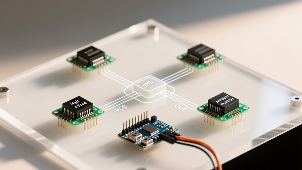
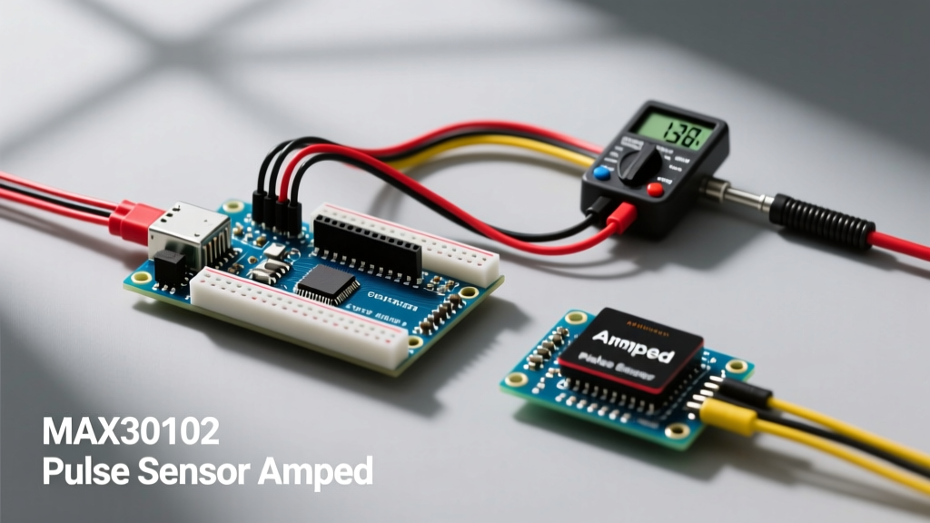
Building an arduino heart sensor is a rite of passage for bio-signal enthusiasts, but achieving clinical-grade accuracy requires navigating a minefield of ambient light noise, motion artifacts, and logic-level mismatches. Photoplethysmography (PPG) measures blood volume changes in the microvascular bed of tissue using light. When integrating PPG modules with microcontrollers, makers generally choose between two dominant architectures: the analog Pulse Sensor Amped and the digital MAX30102.
In this 2026 integration guide, we dissect the electrical characteristics, wiring topologies, and digital signal processing (DSP) requirements for both modules. Whether you are prototyping a wearable fitness tracker or a medical IoT device, understanding the hardware limitations of your chosen sensor is critical to preventing data dropout and I2C bus lockups.
Hardware Comparison Matrix
Before writing a single line of C++, you must evaluate the silicon. The table below contrasts the genuine specifications of both sensor architectures.
| Feature | Pulse Sensor Amped (Analog) | MAX30102 (Digital I2C) |
|---|---|---|
| Signal Output | Analog Voltage (0-5V or 0-3.3V) | Digital (18-bit ADC via I2C) |
| Light Source | Green LED (530nm) | Red (660nm) & IR (880nm) LEDs |
| Internal Processing | MCP6001 Op-Amp (Hardware filtering) | 32-Sample FIFO, Ambient Light Cancellation |
| Operating Voltage | 3.3V to 5V | 1.8V (Internal LDO) / 3.3V I2C Logic |
| Typical Cost (2026) | $24.95 (Genuine) / $4 (Clone) | $8.00 (SparkFun) / $3 (Generic) |
The Analog Route: Pulse Sensor Amped Integration
The Pulse Sensor Amped relies on a hardware-based analog filtering circuit. It utilizes a green LED and a phototransistor, feeding the raw signal into an MCP6001 operational amplifier configured to isolate the AC component (the pulsatile blood flow) from the DC component (baseline tissue absorption).
Wiring and ADC Sampling
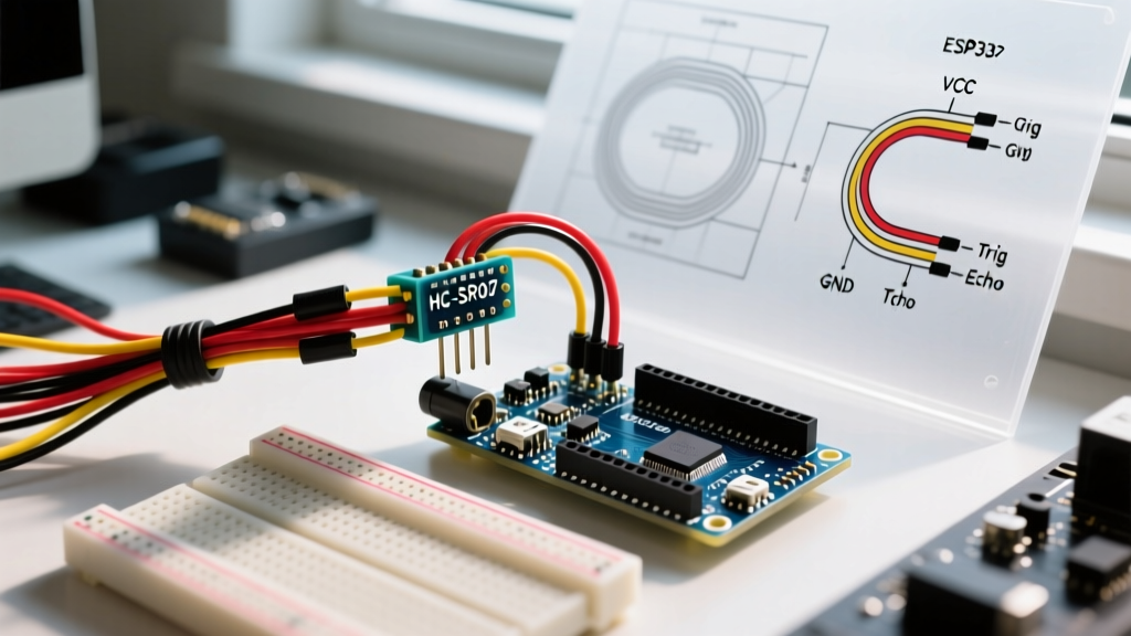
Because the module outputs a conditioned analog signal, it interfaces directly with the Arduino's 10-bit ADC (Analog-to-Digital Converter). Connect the Signal pin to A0, VCC to 5V, and GND to GND.
The critical failure mode in analog PPG is an inadequate sampling rate. To accurately capture a heart rate up to 220 BPM (3.66 Hz), the Nyquist-Shannon sampling theorem dictates a minimum sampling rate of 7.32 Hz. However, to resolve the dicrotic notch and systolic peaks accurately, you must sample at a minimum of 100 Hz. Avoid using delay() in your main loop; instead, use hardware timers or the micros() function to enforce a strict 10ms sampling interval.
The Digital Route: MAX30102 I2C Integration
The MAX30102 is a highly integrated pulse oximetry and heart-rate sensor. According to the Analog Devices MAX30102 specifications, it features an 18-bit ADC with a 32-sample FIFO buffer and programmable LED current drivers. This shifts the burden of signal conditioning from hardware op-amps to software DSP.
The 5V to 3.3V Logic Level Trap
The most catastrophic mistake makers make when wiring a MAX30102 to an Arduino Uno or Nano is ignoring logic levels. The MAX30102 I2C pins are strictly 3.3V tolerant. Connecting them directly to a 5V Arduino's SDA/SCL pins will degrade the sensor's internal ESD protection diodes, eventually leading to a permanent I2C bus short.
You must use a bi-directional logic level shifter (such as a BSS138-based module) between the Arduino and the sensor. As detailed in the SparkFun MAX3010x Hookup Guide, ensuring clean 3.3V logic transitions is mandatory for stable I2C communication.
I2C Configuration and FIFO Management
The MAX30102 operates on a hardcoded I2C address of 0x57. When utilizing the Arduino Wire Library, set the I2C clock speed to 400 kHz (Fast Mode) to drain the FIFO buffer before it overflows.
- LED Current: Start with a Red LED current of
0x1F(approx. 6.4mA). If the signal clips (maxes out the 18-bit ADC at 262143), lower the current. If the signal is lost in the noise floor, increase it up to0x50. - Sample Averaging: Set the sample averaging to 4. This provides a good balance between noise reduction and FIFO read speed.
- Heart Rate Mode: For pure BPM tracking, disable the IR LED and run in "Heart Rate Mode" (Red LED only) to save power and reduce I2C bus traffic.
Digital Signal Processing (DSP) for BPM Extraction
Raw PPG data is incredibly noisy. Motion artifacts and ambient light leakage can easily mimic a heartbeat. To extract accurate Beats Per Minute (BPM), you must implement a digital bandpass filter.
- DC Removal: Apply a high-pass filter with a cutoff of 0.5 Hz to remove baseline wander caused by respiration and slow finger movements.
- Low-Pass Filtering: Apply a low-pass filter with a cutoff of 3.5 Hz (equivalent to 210 BPM) to eliminate high-frequency electromagnetic interference (EMI) and muscle tremor noise.
- Peak Detection: Implement a dynamic thresholding algorithm. Instead of a fixed voltage threshold, calculate a moving average of the signal's amplitude over a 3-second window. A valid systolic peak must exceed this moving average by at least 30% and be followed by a refractory period of at least 300ms (preventing double-counting of the dicrotic notch).
Troubleshooting Common Edge Cases
Motion Artifacts and Sensor Placement
PPG sensors require consistent tissue contact. If the Arduino heart sensor is strapped too loosely, ambient 50Hz/60Hz AC mains light will flood the photodetector. The MAX30102 has built-in ambient light cancellation (ALC), but it requires the sensor to be completely shielded from external light sources. Use an opaque silicone shroud or electrical tape to seal the sensor against the skin.
I2C Bus Lockups on Generic Clone Boards
Many $3 generic MAX30102 breakout boards feature incorrect pull-up resistors on the I2C lines. They often use 10kΩ resistors instead of the recommended 4.7kΩ. At 400 kHz I2C speeds, the RC time constant created by 10kΩ resistors and the bus capacitance causes the SDA/SCL rise times to fail, resulting in Wire.endTransmission() returning error code 1 (data too long to fit in transmit buffer) or 4 (other error). If you experience intermittent I2C timeouts, solder 4.7kΩ resistors directly between the 3.3V line and the SDA/SCL pins on the breakout board.
Conclusion
Choosing the right arduino heart sensor depends entirely on your processing constraints. If you are using a basic Arduino Uno and want immediate, analog peak-detection without complex I2C FIFO management, the Pulse Sensor Amped (or a high-quality clone) is the superior choice. However, if you are building a battery-powered wearable using an ESP32 or Arduino Nano 33 IoT and require SpO2 capabilities alongside high-resolution BPM tracking, the MAX30102 is the undisputed industry standard. By respecting logic levels, enforcing strict sampling intervals, and implementing proper digital bandpass filtering, you can achieve medical-grade biometric tracking on a maker budget.