
Beyond the Single LED: A Multi-Peripheral Approach to Distance Sensing
Most introductory tutorials treat the ultrasonic sensor with LED Arduino simple project as a binary exercise: an object gets close, and a single LED turns on. While this teaches basic digital I/O, it completely ignores the realities of modern embedded systems. In 2026, even basic DIY projects require multi-peripheral management—balancing current draw, avoiding blocking code, and managing pinout constraints.
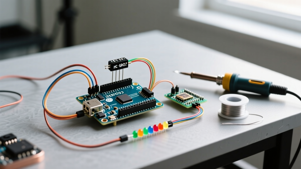
In this guide, we elevate the classic distance sensor project into a functional 5-segment LED bar graph distance meter. By treating this as a multi-peripheral setup, we will cover power budgeting, non-blocking timing logic, and the acoustic physics required to make your sensor reliable in real-world environments.
Bill of Materials & 2026 Component Selection
To build a robust circuit, we must move past outdated components. While the HC-SR04 has been the hobbyist standard for a decade, its 5V-only logic and lack of temperature compensation make it a liability in multi-voltage setups. We recommend the US-100 for modern builds.
- Microcontroller: Arduino Uno R4 Minima (Approx. $22.00) - Features a 48MHz Arm Cortex-M4, offering vastly superior timer resolution for ultrasonic pulse measurement compared to the legacy Uno R3.
- Sensor: US-100 Ultrasonic Distance Sensor (Approx. $6.50) - Natively supports 2.4V to 5.5V logic, eliminating the need for voltage dividers on 3.3V boards, and features a hardware UART mode.
- Display Array: Kingbright DC-10EWA 10-Segment LED Bar Graph (Approx. $1.80) - We will use 5 of the 10 segments to create a proximity meter.
- Current Limiting: 5x 220Ω Carbon Film Resistors (1/4W) - Essential for protecting both the LEDs and the microcontroller's GPIO pins.
- Wiring: 22 AWG solid core hookup wire and a standard 400-point solderless breadboard.
Why the US-100 Outperforms the HC-SR04
The HC-SR04 relies on a basic 555-timer-style circuit to generate its 40kHz burst. If the ambient temperature shifts, the speed of sound changes, but the HC-SR04's hardcoded timing math does not. The US-100 includes onboard compensation and allows you to remove a jumper on the back to switch from PWM trigger mode to a continuous Serial (UART) output mode, freeing up GPIO pins for other peripherals.
Power Budgeting & Pin Allocation Matrix
When wiring multiple peripherals, exceeding the microcontroller's per-pin or total VCC current limits is the most common cause of erratic sensor readings and brownout resets. Below is the calculated power budget for our setup based on the Arduino Uno R4 Minima specifications.
| Component | Operating Voltage | Typical Current Draw | Peak Current Draw | Assigned GPIO Pins |
|---|---|---|---|---|
| Uno R4 Minima (Base) | 5V | 45 mA | 45 mA | N/A |
| US-100 Sensor | 3.3V - 5V | 2 mA (Standby) | 15 mA (Ping) | D7 (Trig), D8 (Echo) |
| 5x Bar Graph LEDs | 2.1V (Forward) | 12 mA (per LED) | 60 mA (All 5 On) | D2, D3, D4, D5, D6 |
| Total System Peak | 5V (USB) | ~120 mA (Well under 500mA USB limit) | N/A | |
Expert Note: Never wire multiple LEDs in parallel to a single GPIO pin. A standard Arduino GPIO pin is limited to 20mA continuous (absolute max 25mA). Always use individual resistors and individual pins, or shift registers for larger arrays.
Step-by-Step Multi-Peripheral Wiring Guide
- Place the Microcontroller & Breadboard: Ensure the breadboard power rails are continuous. If using a full-size board, bridge the center gap of the VCC and GND rails with jumper wires.
- Wire the US-100 Sensor: Connect VCC to the Arduino 5V pin and GND to the breadboard ground rail. Connect the Trig pin to Arduino D7 and the Echo pin to Arduino D8. Leave the UART jumper on the back of the US-100 in place for standard PWM trigger mode.
- Prepare the LED Array: Insert the Kingbright bar graph into the breadboard, straddling the center trench. Identify Pin 1 (usually marked with a small dot or beveled edge on the casing).
- Install Current Limiting Resistors: Connect a 220Ω resistor to the anode (positive) leg of the first 5 segments. Connect the other end of each resistor to Arduino digital pins D2 through D6, respectively.
- Complete the Ground Circuit: Wire all corresponding cathode (negative) legs of the LED segments to the common ground rail.
Non-Blocking C++ Firmware Logic
The biggest mistake beginners make when building an ultrasonic sensor with LED Arduino simple circuit is relying on the delay() function or allowing the pulseIn() function to block the main loop for hundreds of milliseconds. According to the official Arduino pulseIn reference, if no pulse is received, the function will hang until the timeout is reached. We enforce a strict 5000-microsecond timeout to keep the loop responsive.
// Pin Definitions
const int trigPin = 7;
const int echoPin = 8;
const int ledPins[] = {2, 3, 4, 5, 6};
const int numLeds = 5;

// Timing Variables
unsigned long lastPingTime = 0;
const long pingInterval = 60; // Ping every 60ms (approx 16Hz update rate)

void setup() {
  pinMode(trigPin, OUTPUT);
  pinMode(echoPin, INPUT);
  for (int i = 0; i < numLeds; i++) {
    pinMode(ledPins[i], OUTPUT);
    digitalWrite(ledPins[i], LOW);
  }
}

void loop() {
  unsigned long currentMillis = millis();

  // Non-blocking sensor trigger
  if (currentMillis - lastPingTime >= pingInterval) {
    lastPingTime = currentMillis;

    // Send 10us trigger pulse
    digitalWrite(trigPin, LOW);
    delayMicroseconds(2);
    digitalWrite(trigPin, HIGH);
    delayMicroseconds(10);
    digitalWrite(trigPin, LOW);

    // Read echo with strict 5000us timeout to prevent blocking
    long duration = pulseIn(echoPin, HIGH, 5000);

    // Calculate distance (Speed of sound at 20C = 343 m/s -> 0.0343 cm/us)
    // Divide by 2 for round-trip
    float distanceCm = (duration * 0.0343) / 2.0;

    updateBarGraph(distanceCm);
  }
}

void updateBarGraph(float dist) {
  // Map distance thresholds (in cm) to LED states
  // Closer than 10cm = 5 LEDs, > 50cm = 0 LEDs
  int ledsToLight = 0;
  if (dist > 0 && dist <= 10) ledsToLight = 5;
  else if (dist <= 20) ledsToLight = 4;
  else if (dist <= 30) ledsToLight = 3;
  else if (dist <= 40) ledsToLight = 2;
  else if (dist <= 50) ledsToLight = 1;

  for (int i = 0; i < numLeds; i++) {
    if (i < ledsToLight) {
      digitalWrite(ledPins[i], HIGH);
    } else {
      digitalWrite(ledPins[i], LOW);
    }
  }
}
Acoustic Physics & Temperature Compensation
The hardcoded multiplier 0.0343 in the code above assumes an ambient temperature of exactly 20°C (68°F). However, the speed of sound in dry air is governed by the equation v = 331.3 + (0.606 × T), where T is temperature in Celsius.
If you deploy this sensor in an unheated garage at 0°C, the speed of sound drops to 331.3 m/s (0.0331 cm/µs). Over a 50cm distance, this temperature delta introduces a measurement error of nearly 1.8 cm. For precision multi-peripheral setups—such as a liquid level monitor or a robotic obstacle avoidance array—you must integrate a peripheral like the BME280 I2C temperature/pressure sensor to dynamically adjust the speed of sound multiplier in real-time.
Real-World Troubleshooting & Edge Cases
1. Phantom Echoes and Cross-Talk
If you eventually scale this project to include multiple ultrasonic sensors, firing them simultaneously will cause cross-talk, where Sensor A reads the acoustic bounce intended for Sensor B. The Fix: Implement a sequential firing delay of at least 30ms between sensor pings, or angle the sensors more than 15 degrees away from each other to rely on the natural directional attenuation of the 40kHz mesh grid.
2. Acoustic Shadowing and Soft Targets
Ultrasonic sensors rely on acoustic impedance mismatch to create a bounce. Soft, porous materials like acoustic foam, heavy curtains, or winter clothing will absorb the 40kHz wave rather than reflect it, resulting in a timeout (0 cm reading).
Field Tip: If your project requires detecting soft targets (e.g., a person walking behind a curtain), ultrasonic is the wrong technology. Pivot to a 24GHz mmWave radar sensor like the HLK-LD2410, which penetrates soft materials and drywall entirely.
3. Breadboard Ground Bounce
When the 5 LEDs switch on simultaneously, they draw a sudden 60mA spike. On cheap, oxidized solderless breadboards, this causes a momentary voltage drop on the ground rail (ground bounce). The US-100's internal comparator may misinterpret this sag, triggering false echo readings. The Fix: Use a dedicated decoupling capacitor (100µF electrolytic) placed directly across the VCC and GND pins of the ultrasonic sensor to buffer transient current demands.
Next Steps: Expanding the Peripheral Bus
Now that you have mastered a stable, non-blocking ultrasonic sensor with LED Arduino simple foundation, the next logical step is integrating an I2C display. Because the US-100 uses standard GPIO (or hardware UART), your I2C pins (A4/A5 on the Uno R4) remain completely free. You can seamlessly add a 0.96-inch SSD1306 OLED to log historical distance data or display the real-time temperature-compensated calculations without rewriting your core timing logic.