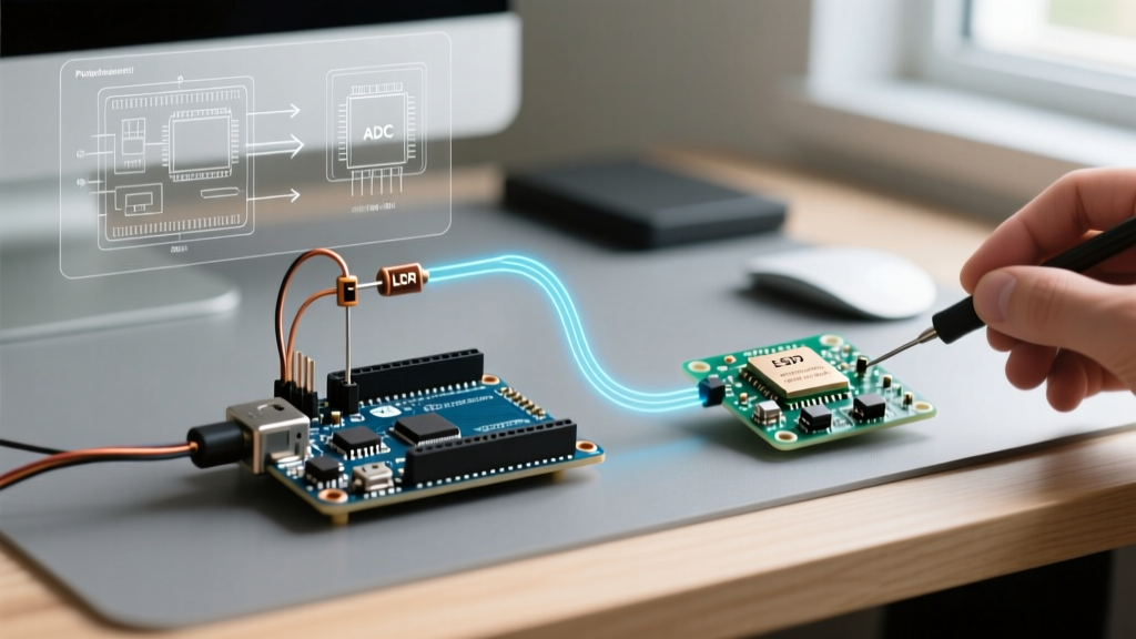

The Reality of Raw LDR Data on Microcontrollers
When hobbyists first wire up an LDR resistor Arduino circuit, the standard approach is to use a simple voltage divider and call analogRead(). While this works for basic night-light triggers, it fails completely in precision applications like photography light metering, automated greenhouse shading, or display backlight dimming. Raw ADC (Analog-to-Digital Converter) readings from Light Dependent Resistors are notoriously noisy, non-linear, and susceptible to 100Hz/120Hz ripple from artificial lighting.
To get reliable, actionable Lux data, you do not just need the right hardware; you need a dedicated software driver. In this guide, we will engineer a custom C++ driver class for your LDR, implement a moving-average ring buffer to defeat mains flicker, and map the non-linear resistance curve to real-world Lux values.
Hardware Baseline: The Geometric Mean Resistor
Before writing the driver, we must ensure the hardware voltage divider is optimized for the microcontroller's ADC range. The most common hobbyist LDR is the GL5528 (Cadmium Sulfide). It has a dark resistance of ~1 MΩ and a bright light (10 Lux) resistance of ~10 kΩ to 20 kΩ.
According to the SparkFun Voltage Divider Tutorial, to maximize the voltage swing across the widest range of expected lighting conditions, your fixed pull-down resistor should be the geometric mean of the LDR's minimum and maximum expected resistances.
Formula: R_fixed = √(R_dark × R_light)
Calculation: √(1,000,000 × 2,000) ≈ 44,721 Ω
While a 47 kΩ resistor is mathematically ideal for the absolute extremes, most indoor applications operate between 50 and 500 Lux. In this range, the GL5528 sits between 5 kΩ and 15 kΩ. Therefore, a standard 10 kΩ 1/4W carbon film resistor (costing roughly $0.02) is the pragmatic choice for 5V logic, centering the voltage output near 2.5V at typical room illumination.
Common LDR Specifications Matrix
| LDR Model | Diameter | Resistance @ 10 Lux | Gamma (γ) | Typical Cost (2026) |
|---|---|---|---|---|
| GL5516 | 5mm | 5kΩ - 10kΩ | 0.60 | $0.08 |
| GL5528 | 5mm | 10kΩ - 20kΩ | 0.70 | $0.12 |
| GL5537-1 | 7mm | 20kΩ - 30kΩ | 0.85 | $0.18 |
| Advanced Photonix PDV-P9203 | 9mm | 400Ω - 1.2kΩ | 0.75 | $1.45 |
The Mains Flicker Problem
If you sample an LDR in a room lit by AC-powered LEDs or fluorescent tubes, your Arduino analogRead() Reference data will look like a jagged sawtooth wave. AC mains power operates at 50Hz (Europe/Asia) or 60Hz (North America). Because light bulbs rectify this AC, they flicker at 100Hz or 120Hz.
If your code samples the LDR asynchronously, the ADC will catch random peaks and troughs of this light ripple, resulting in ±15% fluctuations in your Lux calculations. The solution is not hardware filtering (which slows response time), but software oversampling synchronized to cancel the ripple, or applying a robust digital low-pass filter.
Writing the Custom LDR Driver Class
Instead of scattering analogRead() calls throughout your main loop, we encapsulate the sensor logic into an LDR_Driver class. This driver handles the ADC polling, applies a ring-buffer moving average, and executes the Steinhart-Hart-like empirical formula for LDR Lux conversion.
The resistance-to-Lux formula is: Lux = (R_ldr / A)^(-1/γ), where A is a constant (typically ~500,000 for GL55xx) and γ (gamma) is the slope of the log-log resistance curve.
#ifndef LDR_DRIVER_H
#define LDR_DRIVER_H

#include <Arduino.h>

class LDR_Driver {
  private:
    uint8_t pin;
    float gamma;
    float a_factor;
    int adc_max;
    float pull_down_res;

    // Ring buffer for filtering 120Hz flicker
    static const int BUFFER_SIZE = 16;
    float readings[BUFFER_SIZE];
    int readIndex = 0;
    float total = 0;

    float getRawResistance() {
      float adc_avg = 0;
      // Oversample 16 times to reduce ADC quantization noise
      for(int i = 0; i < 16; i++) {
        adc_avg += analogRead(this->pin);
        delayMicroseconds(500);
      }
      adc_avg /= 16.0;

      // Prevent division by zero at max brightness
      if (adc_avg >= this->adc_max - 1) adc_avg = this->adc_max - 1;

      // Voltage divider math: R_ldr = R_pull * ((ADC_max / ADC_val) - 1)
      return this->pull_down_res * ((this->adc_max / adc_avg) - 1.0);
    }

  public:
    LDR_Driver(uint8_t p, float g, float a, int max_adc, float r_pull) {
      this->pin = p;
      this->gamma = g;
      this->a_factor = a;
      this->adc_max = max_adc;
      this->pull_down_res = r_pull;

      // Initialize buffer
      for(int i=0; i<BUFFER_SIZE; i++) this->readings[i] = 0;
    }

    float getLux() {
      float r = getRawResistance();
      float lux = pow((r / this->a_factor), -1.0 / this->gamma);

      // Update ring buffer
      this->total = this->total - this->readings[this->readIndex];
      this->readings[this->readIndex] = lux;
      this->total = this->total + this->readings[this->readIndex];
      this->readIndex = (this->readIndex + 1) % BUFFER_SIZE;

      return this->total / BUFFER_SIZE;
    }
};
#endif
Implementing the Driver in Your Sketch
To use this driver on a standard 5V Arduino Uno (10-bit ADC, max value 1023) with a GL5528 and a 10kΩ pull-down resistor, your setup looks like this:
#include "LDR_Driver.h"

// Pin A0, Gamma 0.7, A-Factor 500000, 10-bit ADC (1024), 10k Pull-down
LDR_Driver myLightSensor(A0, 0.7, 500000.0, 1024, 10000.0);

void setup() {
  Serial.begin(115200);
  // Note: For ESP32-S3 users in 2026, change 1024 to 4096 for 12-bit ADC,
  // and use analogReadResolution(12) in setup.
}

void loop() {
  float current_lux = myLightSensor.getLux();
  Serial.print("Stabilized Lux: ");
  Serial.println(current_lux);
  delay(50); // 20Hz update rate
}
Alternative: Leveraging Existing Filter Libraries
If you prefer not to write a custom ring buffer, you can combine the raw voltage divider math with established signal processing libraries. The Rob Tillaart RunningAverage Library is an industry standard for Arduino sensor smoothing. By feeding the raw ADC values into a 20-element RunningAverage instance, you effectively create a low-pass filter that chops off the 120Hz lighting ripple while preserving the sensor's reaction to actual environmental changes (like a cloud passing over a solar array).
However, be aware that generic running average libraries consume slightly more SRAM than the optimized ring-buffer approach shown in our custom driver, which is a critical consideration if you are deploying on an ATtiny85 with only 512 bytes of RAM.
Edge Cases and 2026 Hardware Realities
When deploying LDR circuits in the field, keep these failure modes in mind:
- Thermal Drift: CdS (Cadmium Sulfide) LDRs exhibit a temperature coefficient of roughly -0.5% per °C. If your sensor is mounted inside a hot electronics enclosure, your Lux readings will artificially drop. Always mount the LDR outside the primary heat envelope.
- ADC Saturation: In direct sunlight (100,000+ Lux), the GL5528 resistance drops to ~500Ω. With a 10kΩ pull-down, the voltage drops to 0.23V. On a 5V system, this is only ~47 ADC steps, resulting in terrible resolution at high brightness. If outdoor tracking is required, swap the 10kΩ pull-down for a 1kΩ resistor to shift the dynamic range.
- RoHS Compliance Shifts: As of 2026, commercial manufacturing has largely moved away from Cadmium-based LDRs due to strict RoHS enforcement. If you are transitioning a prototype to a commercial PCB, consider replacing the GL5528 with an analog phototransistor (like the TEPT5600) or an I2C digital ambient light sensor (like the VEML7700), which offer linear outputs and built-in 50/60Hz hardware rejection.
Summary
Treating an LDR resistor Arduino setup as a simple analog input is a recipe for erratic behavior. By calculating the geometric mean for your voltage divider, understanding the gamma curve of your specific CdS cell, and implementing a software ring-buffer driver, you transform a $0.12 passive component into a stable, precision light meter capable of driving complex automation logic.


