
Beyond the Breadboard: The Reality of 40kHz Acoustics
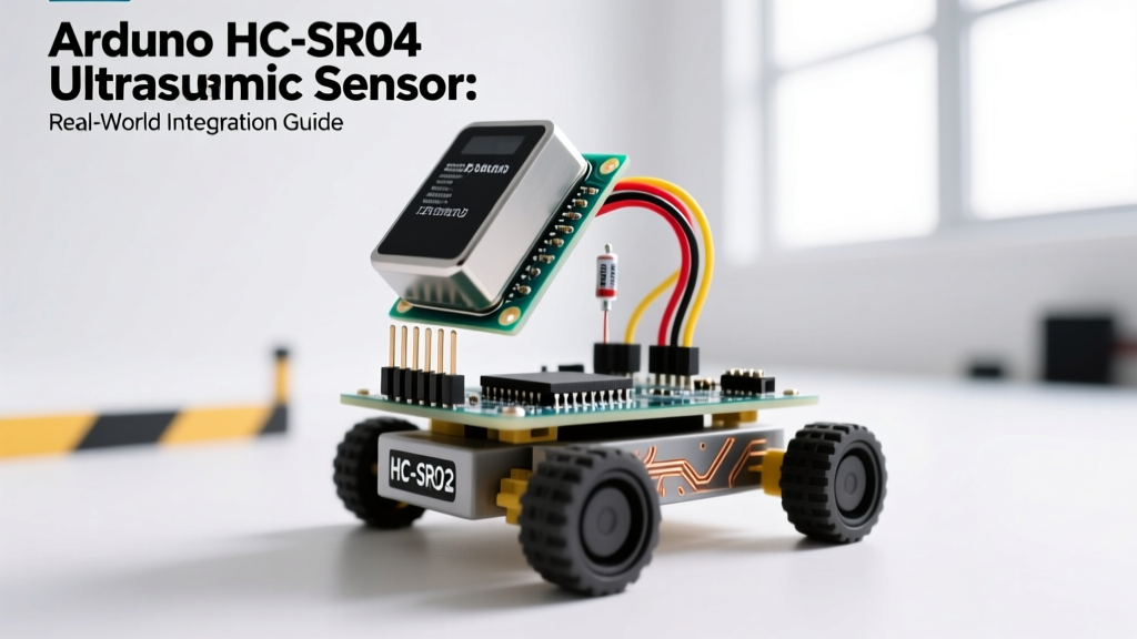
Most introductory electronics tutorials treat the Arduino HC SR04 ultrasonic sensor as a flawless, plug-and-play distance tool. You wire it to a 5V Arduino Uno, run a basic ping sketch, and measure the distance to your hand on a quiet desk. But deploying this $2 sensor in real-world environments—like an overhead water tank, an outdoor robotic chassis, or a damp garage parking assistant—exposes its inherent physical and electrical limitations. In 2026, with the maker community largely migrating to 3.3V logic ecosystems like the ESP32-S3 and Raspberry Pi Pico 2 (RP2350), integrating this legacy 5V module requires deliberate hardware protection and advanced software filtering.
This guide bridges the gap between hobbyist tutorials and professional deployment, focusing on temperature compensation, logic-level translation, and acoustic noise rejection.
The Physics of Sound and the Temperature Drift Problem
The HC-SR04 calculates distance by measuring the time-of-flight (ToF) of a 40kHz acoustic burst. The fundamental formula is Distance = (Time × Speed of Sound) / 2. However, the speed of sound in air is not a static constant; it fluctuates significantly with ambient temperature and humidity.
According to thermodynamic principles documented by the Engineering Toolbox, the speed of sound in dry air at 0°C is approximately 331.3 m/s, increasing by about 0.606 m/s for every 1°C rise in temperature. If your code hardcodes the speed of sound at 343 m/s (the standard for 20°C), a sensor deployed in an unheated garage at 0°C will introduce a 3.5% error. Over a 4-meter range, that equates to a 14 cm measurement ghost—enough to cause a collision in robotics or a false overflow trigger in fluid monitoring.
Implementing Real-Time Temperature Compensation
To achieve sub-centimeter accuracy in variable environments, you must pair the HC-SR04 with a digital temperature sensor like the DS18B20 or BME280. Update your distance calculation dynamically:
- Step 1: Read ambient temperature in Celsius (e.g.,
T = 15.5). - Step 2: Calculate the current speed of sound:
v = 331.3 + (0.606 * T). - Step 3: Convert to cm/µs:
v_cm_us = v / 10000. - Step 4: Calculate distance:
distance = (pulse_duration * v_cm_us) / 2.
Hardware Matrix: Standard vs. Industrial Upgrades
While the standard HC-SR04 is fine for indoor prototyping, hostile environments demand hardware upgrades. Below is a deployment matrix comparing the standard module against common real-world alternatives.
| Sensor Model | Avg. Cost (2026) | IP Rating / Build | Blind Spot | Best Application |
|---|---|---|---|---|
| Standard HC-SR04 | $1.50 - $2.50 | None (Open Mesh) | ~2 cm | Indoor robotics, dry bin level sensing |
| JSN-SR04T V2.0 | $4.00 - $6.00 | IP67 (Sealed Probe) | ~20 cm | Water tanks, outdoor automotive, damp soil |
| MaxBotix LV-MaxSonar-EZ | $28.00 - $35.00 | IP67 (Optional) | 0 cm (To face) | Industrial automation, precision fluid dynamics |
Interfacing with 3.3V Microcontrollers (ESP32 / RP2040)
A critical failure mode in modern deployments is frying the GPIO pins of 3.3V microcontrollers. The HC-SR04's ECHO pin outputs a 5V HIGH signal when triggered. Feeding 5V directly into an ESP32 or Raspberry Pi Pico GPIO will eventually degrade the silicon, leading to erratic reads or permanent pin failure.
You must implement a voltage divider. As detailed in SparkFun's voltage divider guide, you can step down the 5V signal to a safe 3.3V using two resistors.
The 3.3V Logic Protection Circuit
- R1 (High-Side): Connect a 1kΩ resistor between the HC-SR04
ECHOpin and the MCU GPIO pin. - R2 (Low-Side): Connect a 2kΩ resistor between the MCU GPIO pin and common Ground (GND).
- Result:
V_out = 5V * (2k / (1k + 2k)) = 3.33V. This is perfectly within the 3.3V logic HIGH threshold while protecting the silicon.
Pro-Tip for High-Noise Environments: If your sensor is mounted more than 50cm away from the microcontroller, the ECHO line acts as an antenna for EMI (Electromagnetic Interference). Add a 100nF ceramic capacitor in parallel with the R2 resistor to create a low-pass RC filter, shaving off high-frequency noise spikes before they reach the MCU.
Software: Defeating Acoustic Multipath and Ringing
The standard Arduino pulseIn() function is blocking and highly susceptible to acoustic anomalies. In a garage parking assistant, the 15-degree beam angle of the HC-SR04 will inevitably strike the side walls or floor before hitting the car bumper. This "multipath" reflection returns a delayed echo, causing the sensor to report the car is further away than it actually is.
Implementing a Median Filter
Do not use a simple moving average; an average will smooth out the data but will still be skewed by massive multipath outliers. Instead, use a Median Filter. By taking 5 rapid samples, sorting them, and selecting the middle value, you completely discard both the premature acoustic ringing (abnormally short reads) and the multipath wall bounces (abnormally long reads).
For a 2026 production-level sketch, trigger the sensor every 25ms (allowing the 40kHz burst to dissipate and preventing acoustic crosstalk), collect 5 samples into an array, sort the array, and return array[2].
Real-World Case Studies and Edge Cases
Case Study 1: Overhead Water Tank Level Monitoring
The Scenario: Mounting a JSN-SR04T (waterproof variant) at the top of a 1000-liter polyethylene water tank to monitor volume via an ESP32 MQTT node.
The Edge Case: Condensation. As water evaporates and cools the tank ceiling, water droplets form directly on the transducer mesh, scattering the 40kHz waves and returning a false "tank full" reading (0 cm).
The Solution: Apply a hydrophobic nano-coating (like NeverWet) to the transducer face. Additionally, angle the sensor 2 degrees off absolute vertical so gravity pulls condensation droplets off the center acoustic axis.
Case Study 2: Garage Parking Assistant
The Scenario: Wall-mounted HC-SR04 to stop a vehicle exactly 30cm from the workbench.
The Edge Case: License plate angles and bumper curves deflect the acoustic burst away from the receiver.
The Solution: Mount the sensor at the exact height of the vehicle's flat license plate frame, not the sloped hood. Use a 3D-printed acoustic baffle (a simple 5cm deep tube) around the receiver transducer to narrow the beam angle from 15 degrees down to roughly 8 degrees, eliminating floor-bounce multipath errors.
Troubleshooting Matrix: Common Failure Modes
| Symptom | Probable Root Cause | Engineering Fix |
|---|---|---|
| Readings stuck at 0 cm or 400+ cm | Timeout or VCC sag during transmit burst. | Add a 470µF electrolytic capacitor across VCC and GND at the sensor to handle the 15mA transmit spike. |
| Random massive spikes in distance | Multipath reflections or acoustic crosstalk. | Implement median filtering; increase ping interval to 50ms; add acoustic baffling tubes. |
| Consistent offset error (e.g., always +3cm) | Hardcoded speed of sound mismatch or internal DSP delay. | |
| MCU GPIO randomly dies after weeks of use | 5V ECHO back-feeding a 3.3V logic pin. | Verify voltage divider resistor values with a multimeter; ensure R2 is tied to MCU GND, not sensor GND. |
Conclusion
The Arduino HC SR04 ultrasonic sensor remains an unparalleled value proposition for spatial awareness in DIY and prosumer electronics. However, treating it as a flawless digital component rather than an analog acoustic instrument is the primary reason projects fail in the field. By respecting the physics of sound, protecting modern 3.3V logic architectures, and deploying statistical filtering in your firmware, you can elevate this $2 module into a highly reliable, real-world deployment tool.